


D-2
MAINTENANCE
D-2
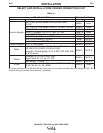
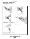
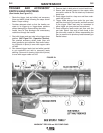
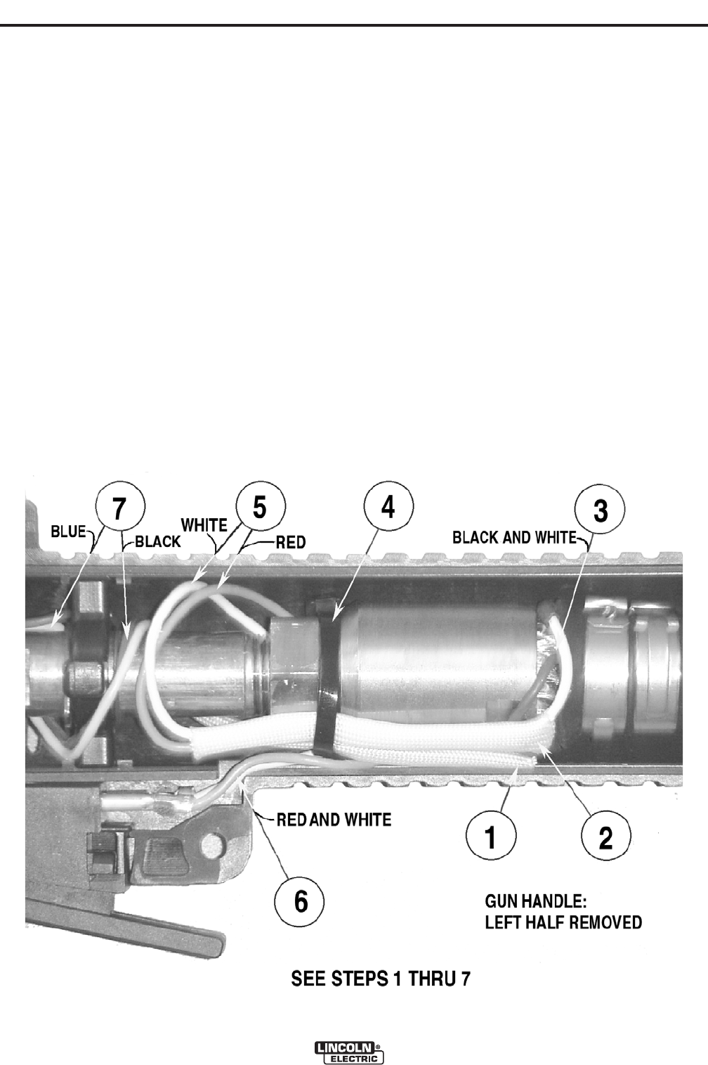
TRIGGER AND ACCESSORY
SWITCH LEAD ROUTINGS
(Gun Handle, See Figure D.1)
• Route the trigger (red and white) and accessory
(blue and black) leads following the steps shown
below. Proper routing:
• Provides adequate slack so that the handle can
rotate to its trigger-up or trigger-down positions
without damaging or disconnecting the leads.
• Avoids fume air flow blockage and unnecessary
restrictions through the handle.
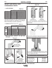
1. Start with trigger and gun tube in the trigger-down
position (See Figure B.1, Operation Section).
Run sleeved accessory switch leads (blue and
black) parallel to gun centerline. Rear end of sleev-
ing (right-side in photo) is even with copper cable
nut end.
2. Run sleeved trigger leads (red and white) parallel
to gun centerline and next to accessory leads
sleeving. Rear end of sleeving (right-side in photo)
is even with copper cable nut end.
3. Remove slack in both pairs of control leads here.
4. Secure both sleeved groups to the copper cable
cone with a cable tie. Do not attach any unsleeved
leads here.
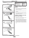
5. Route trigger leads in a loop over and then under-
neath the gun tube.
6. Trigger leads emerge from under the gun tube,
pass thru lead slot in gun handle, and then connect
to the trigger. Either lead may be connected to
either trigger pin (non-polarized connections).
7. Route accessory leads under and then over the
gun tube. Secure free ends of both leads to the
gun tube with a cable tie. When reassembling the
gun, be careful not to pinch any leads between gun
handle halves.
MAGNUM™ PRO 350 and 550 FUME GUNS
FIGURE D.1