


A-2
INSTALLATION
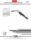
MAGNUM™ PRO 350 and 550 FUME GUNS
A-2
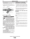
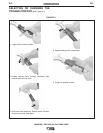
ASSEMBLY OF FUME GUN INTERNAL
PARTS (550 amp model shown)
GUN HANDLE END (Figure A.3, Items 1 thru 7)
1. Two spiders support the handle and allow it to swiv-
el around the gun tube assembly for Trigger-Down
(shown) or Trigger-Up Positions.
2. Gun tube lock (with roll pin) prevents handle over-
rotation to avoid trigger lead damage.
3. Accessory switch leads (blue and black) may serve
as spare trigger leads.
4. Trigger and accessory leads are routed to permit air
flow and avoid lead damage.
5. One-piece copper electrical connector (cone) and
gas hose barb fitting.
6. Copper cable nut for high electrical conductivity.
7. Two clamps (non-reusable) secure the cableʼs core
tube to its hose barb fittings.
UNPACKING THE FUME GUN
Fume guns are factory-assembled and tested. Both
gun models are shipped with a FCAW fume collection
nozzle installed. Contact tips for 0.045 and 3/32”
Diameter Wire are also installed on the 350 and 550
models, respectively. After opening the packaging,
check that it contains 1 fully assembled fume gun, 1
GMAW fume collection nozzle, and 1 instruction man-
ual (IM990).
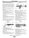
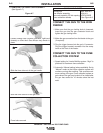
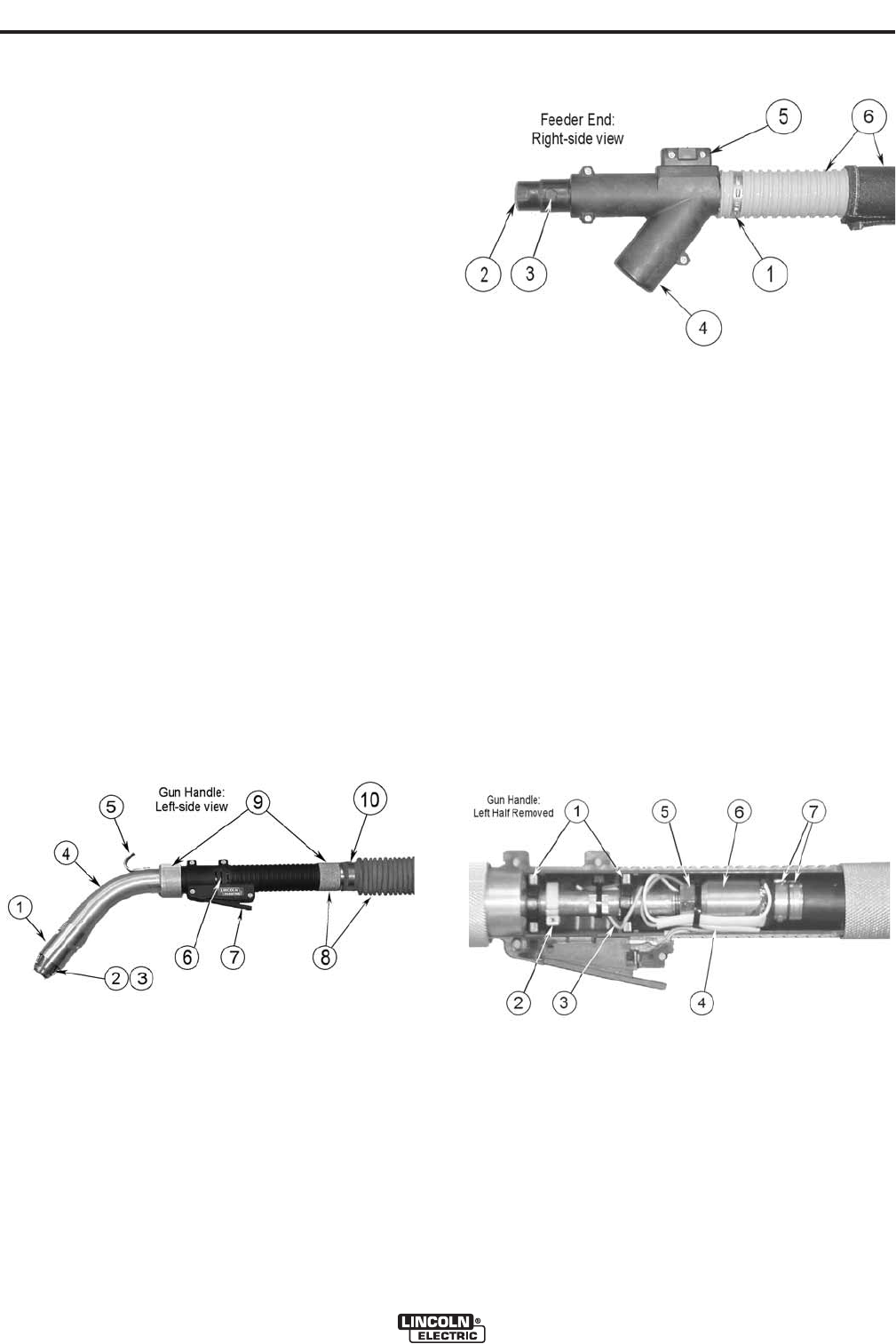
FUME GUN FAMILIARIZATION (550 amp
model shown)
GUN HANDLE (Figure A.1, Items 1 thru 10)
1. 1/8-Turn Fume Collection Nozzle (FCAW self-
shielded version shown).
2. Heavy-Duty Slip-On Gas Nozzle Assembly.
3. Heavy-Duty Gas Diffuser Assembly with Magnum
Pro Contact Tip.
4. Fume Tube Assembly with Integral Gun Hanger and
Locking Collar.
5. Gun Hanger.
6. Handle Cooling Vents.
7. Trigger Assembly (SPST contacts, non-locking) with
Finger Extension. Optional locking trigger assembly
is available.
8. Swivel and Bellows Assemblies increase gun flexi-
bility.
9. Locking Collar & Swivel allow Rapid Selection of
Trigger-Down (shown) or Trigger-Up Positions.
10. Low-Profile Reusable Hose Clamps.
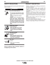
FEEDER END (Figure A.2, Items 1 thru 6)
1. Low-Profile Reusable Hose Clamps.
2. Incoming Connector Assembly: accommodates all
standard Lincoln Magnum 300, 400, and 550 feeder
connection K kits.
3. Gas Plug.
4. Vacuum Connection.
5. Modular Trigger Terminal Housing.
6. Vacuum Hose and Cover. Cover resists hot weld
spatter; can be quickly and easily replaced with
hook & eye closure along its entire length.
FIGURE A.1
FIGURE A.2
FIGURE A.3
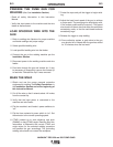
FEEDER END (Figure A.4, Items 1 thru 8)
1. Accessory switch leads (blue and black) may serve
as spare trigger leads.
2. Trigger and accessory leads are routed to permit air
flow and avoid lead damage.
3. One-piece copper electrical connector (cone) and
gas hose barb fitting.
4. Copper cable nut for high electrical conductivity.
5. Two clamps (non-reusable) secure the cableʼs core
tube to its hose barb fittings.