


REMOTE CONTROL
OUTPUT
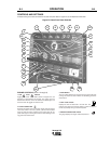
The Vantage is equipped with a 6-pin and a 14-pin connector. The
6-pin connector is for connecting the K857 or K857-1 Remote
Control or for TIG welding, the K870 foot Amptrol or the K936-2
hand Amptrol. When in the CC-STICK, DOWNHILL PIPE, or CV-
WIRE modes and when a remote control is connected to the 6-
pin Connector, the auto-sensing circuit automatically switches the
OUTPUT control from control at the welder to remote control.
When in TOUCH START TIG mode and when a Amptrol is
connected to the 6-Pin Connector, the OUTPUT dial is used to set
the maximum current range of the CURRENT CONTROL of the
Amptrol.
The 14-pin connector is used to directly connect a wire feeder
control cable. In the CV-WIRE mode, when the control cable is
connected to the 14-pin connector, the auto-sensing circuit
automatically makes the Output Control inactive and the wire
feeder voltage control active
NOTE: When a wire feeder with a built in welding voltage
control is connected to the 14-pin connector, do not connect
anything to the 6-pin connector.
--------------------------------------------------------------------------------------
AUXILIARY POWER RECEPTACLES
The auxiliary power capacity of the Vantage is 12kVA of 50Hz
three phase power. All models are protected by an RCD
(Residual Current Device) and a 3 phase 20 amp circuit breaker.
The auxiliary power capacity in watts equivalent to volt-amperes
at unity power factor.
This model has:
1 x 3 phase and neutral Residual Current Device (RCD)
protection (30mA)
1 x 3 phase 20 amp Circuit Breaker
1 x 3 phase 380 volt 18.5 amp
3 x 1 phase 15 amp Circuit Breakers
3 x 1 phase 220 volt 15 amp per outlet
Note: The single-phase outlets are from different phases and
cannot be paralleled.
The auxiliary power receptacles should only be used with three or
four wire earthed type plugs or approved double insulated tools.
The current rating of any plug used with the system must be at
least equal to the current capacity of the associated receptacle.
STANDBY POWER CONNECTIONS
The Vantage is suitable for temporary, standby or emergency
power using the engine manufacturer’s recommended
maintenance schedule.
The Vantage can be permanently installed as a standby power
unit for 380/220 volt (50Hz). Connections must be made by a
licensed electrician who can determine how the 380/220 VAC
power can be adapted to the particular installation and comply
with all applicable electrical codes. The following information can
be used as a guide by the electrician for most applications.
1. Install an isolation switch between the power company meter
and the premises disconnect. (the Vantage and the power
company supplies must not be connected together).
Switch rating must be the same or greater than the customer’s
premises disconnect and service over current protection.
2. Take necessary steps to assure load is limited to the capacity
of the Vantage by installing a 20 amp, 380 VAC three pole
circuit breaker. Loading above the rated output will reduce
output voltage below the allowable -10% of rated voltage which
may damage appliances or other motor-driven equipment and
may result in overheating of the Vantage engine.
3. Install a 20 amp 3 phase plug to the triple-pole circuit breaker
using 2.5
2
mm (minimum) x 4 conductor cable of the desired
length. (The 20 amp, plug is available in the optional KA1373
plug kit).
4. Plug this cable into the 3 phase receptacle on the Vantage
case front.
A-6 INSTALLATION A-6
Vantage 575
WARNING