


Vantage 575
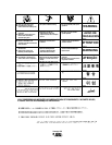
F-14 DIAGRAMS F-14
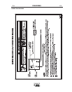
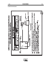
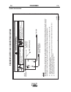
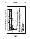
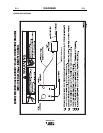
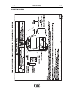
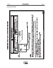
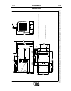
DIMENSION PRINT
TRAILER MOUNTING HOLE LOCATIONS.
*
28.99
736.3
19.63
498.6
6.55
166.4
23.69
601.7
50.38
1279.7
54.44
1382.8
14.63
371.6
37.30
947.4
45.38
1152.7
63.10
1602.7
6.56
166.6
42.00
1066.8
50.81
1290.6
16.85
428
33.53
851.7
32.08
814.8
42.35
1075.7
31.50
800.1
45.67
1160
2.24
56.9
50.15
1273.8
5.86
148.8
46.35
1177.3
*
*
*
*
BOTTOM VIEW OF WELDER BASE.
N.A. CENTER OF GRAVITY WITH OIL IN ENGINE, EMPTY FUEL TANK AND COOLANT IN RADIATOR.
N.A.
M18962-3
A.0 3
6.53
165.9
24.97
634.2
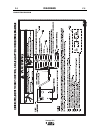
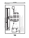
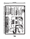
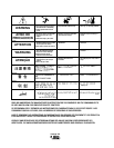
NOTE: This diagram is for reference only. It may not be accurate for all machines covered by this manual. The specific diagram for a particular code is pasted inside the machine on one of the enclosure
panels. If the diagram is illegible, write to the Service Department for a replacement. Give the equipment code number.