


A-3
INSTALLATION
CV-300
A-3
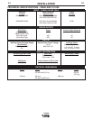
FIELD INSTALLED OPTIONS
For installation of compatible field installed options
(see the ACCESSORIES section of this manual and
refer to the instructions included with those options.
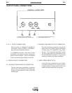
REQUIRED EQUIPMENT-CONTROL
CABLE CONNECTIONS
Follow the instructions below which are appropriate
for the wire feeder that will be used.
LN-7 to CV-300
a) Turn the CV-300 Power switch to the "OFF" posi-
tion.
b) Connect the LN-7 control cable to the wire feeder
receptacle on the CV-300.
c) See OUTPUT CONNECTIONS for connection of
work and electrode cables.
LN-25 to CV-300
a) Turn the CV-300 Power switch to the "OFF" posi-
tion.
b) Plug a K484 jumper plug into the CV-300 wire
feeder receptacle.
c) See OUTPUT CONNECTIONS for connection of
work and electrode cables.
The output terminals are energized at all times when
the K484 is plugged in.
------------------------------------------------------------------------
LN-742 to CV-300
a) Turn the CV-300 Power switch to the "OFF" posi-
tion.
b) Connect the LN-742 control cable to the wire
feeder receptacle on the CV-300.
c) See OUTPUT CONNECTIONS for connection of
work and electrode cables.
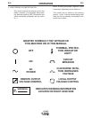
Connection of Remote Control (K857)
NOTE: The K864 Remote Control Adapter is required
to install the K857.
Plug the K864 Remote Control Adapter into the power
source's 14-pin receptacle. Plug the K857 Remote
Control into the 6-pin receptacle of the K864 adapter.
If possible, tape the Remote cable to the heavy output
leads, so they can protect the smaller Remote cable
from damage and abuse.
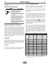
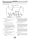
OUTPUT CONNECTIONS
Output cables must have Magnum Twist-Mate™ plugs
for connection to the CV-300. Order K852-95 for con-
necting 2/0-3/0 (70-95 mm2) cables. Refer to S18737
for instructions on installing these plugs.
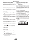
Use the shortest possible cable lengths. See Table
A.1 for recommended cable sizes based on length.
Connect the positive output lead to the terminal
marked "+". The negative output lead can be hooked
to either the low inductance terminal (marked "
") or the high inductance terminal (marked
" ").
WARNING
TABLE A.1
Cable Sizes for Combined Lengths of Copper
Electrode and Work Cable
Machine Size
Lengths up to
150 ft 150 to 200 ft
300 A 100%
(400 A 60%)
2/0 (70mm
2
) 3/0 (95mm
2
)