


A-2
INSTALLATION
CV-300
A-2
Read entire installation section before starting
installation.
SAFETY PRECAUTIONS
SELECT SUITABLE LOCATION
Place the welder where clean cooling air can freely
circulate in through the side louvers and out through
the rear louvers. Dirt, dust or any foreign material that
can be drawn into the welder should be kept at a
minimum. Failure to observe these precautions can
result in excessive operating temperatures and
nuisance shut-downs. Idealarc CV-300 power sources
carry an IP23 enclosure rating. They are rated for use
in damp, dirty environments subject to occasional
falling water such as rain.
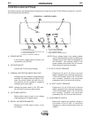
STACKING
The CV-300 may be stacked three-high provided the
bottom machine is on a stable, hard, level surface. Be
sure that the two pins in the roof fit into the slots in the
base of the CV-300 above it.
TILTING
Do not place the machine on a surface that is inclined
enough to create a risk of the machine falling over.
INPUT CONNECTIONS
Be sure the voltage, phase, and frequency of the input
power is as specified on the welder nameplate.
Gain access to the input reconnect panel by removing
the right case side of the CV-300 (side nearest to the
Power switch.)
Have a qualified electrician connect the input leads to
L1, L2, and L3 of the input reconnect panel in accor-
dance with the National Electrical Code, all local
codes, and the connection diagram located on the
inside of the right case side. Use a three phase line.
The frame of the welder must be grounded. A ground
terminal marked with the symbol located on the
base of the machine is provided for this purpose. See
the National Electrical Code for details on proper
grounding methods.
Fuse the input circuit with the recommended super lag
fuses. Choose an input and grounding wire size
according to local codes or use the following table.
"Delay type"
1
circuit breakers may be used in place of
fuses. Using fuses or circuit breakers smaller than
recommended may result in "nuisance" tripping from
welder inrush currents even if not welding at high cur-
rents.
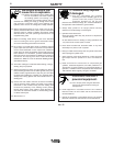
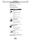
ELECTRIC SHOCK can kill.
• Only qualified personnel should
perform this installation.
• Turn the input power OFF at the discon-
nect switch or fuse box before working on
this equipment.
• Turn the Power switch on the CV-300
“OFF” before connecting or disconnect-
ing output cables, wire feeder or remote
connections, or other equipment.
• Do not touch electrically hot parts.
• Always connect the Idealarc CV-300
grounding terminal (located on the welder
base near the reconnect panel) to a good
electrical earth ground.
WARNING
RECOMMENDED INPUT WIRE AND FUSE SIZES
Input
Voltage /
Frequency
208/60
230/60
460/60
575/60
200/50/60
220/50/60
230/50/60
380/50/60
400/50/60
415/50/60
440/50/60
500/50/60
Input
Ampere
Rating on
Nameplate
66
60
30
24
66
61
58
35
33
32
31
26
Type 75°C
Copper
Ground Wire in
Conduit AWG
(IEC) Sizes
8 (10mm
2
)
8 (10mm
2
)
10 (6mm
2
)
10 (6mm
2
)
8 (10mm
2
)
8 (10mm
2
)
8 (10mm
2
)
10 (6mm
2
)
10 (6mm
2
)
10 (6mm
2
)
10 (6mm
2
)
10 (6mm
2
)
Fuse
(Super Lag)
or Breaker
Size
100
90
50
40
100
90
90
60
50
50
50
40
Type 75°C
Copper Wire in
Conduit AWG
(IEC) Sizes
4 (25 mm
2
)
4 (25 mm
2
)
10 (6mm
2
)
10 (6mm
2
)
4 (25 mm
2
)
4 (25 mm
2
)
4 (25 mm
2
)
8 (10mm
2
)
8 (10mm
2
)
8 (10mm
2
)
10 (6mm
2
)
10 (6mm
2
)
1
Also called “inverse time” or “thermal/magnetic” circuit breakers; circuit
breakers which have a delay in tripping action that decreases as the magni-
tude of the current increases.