


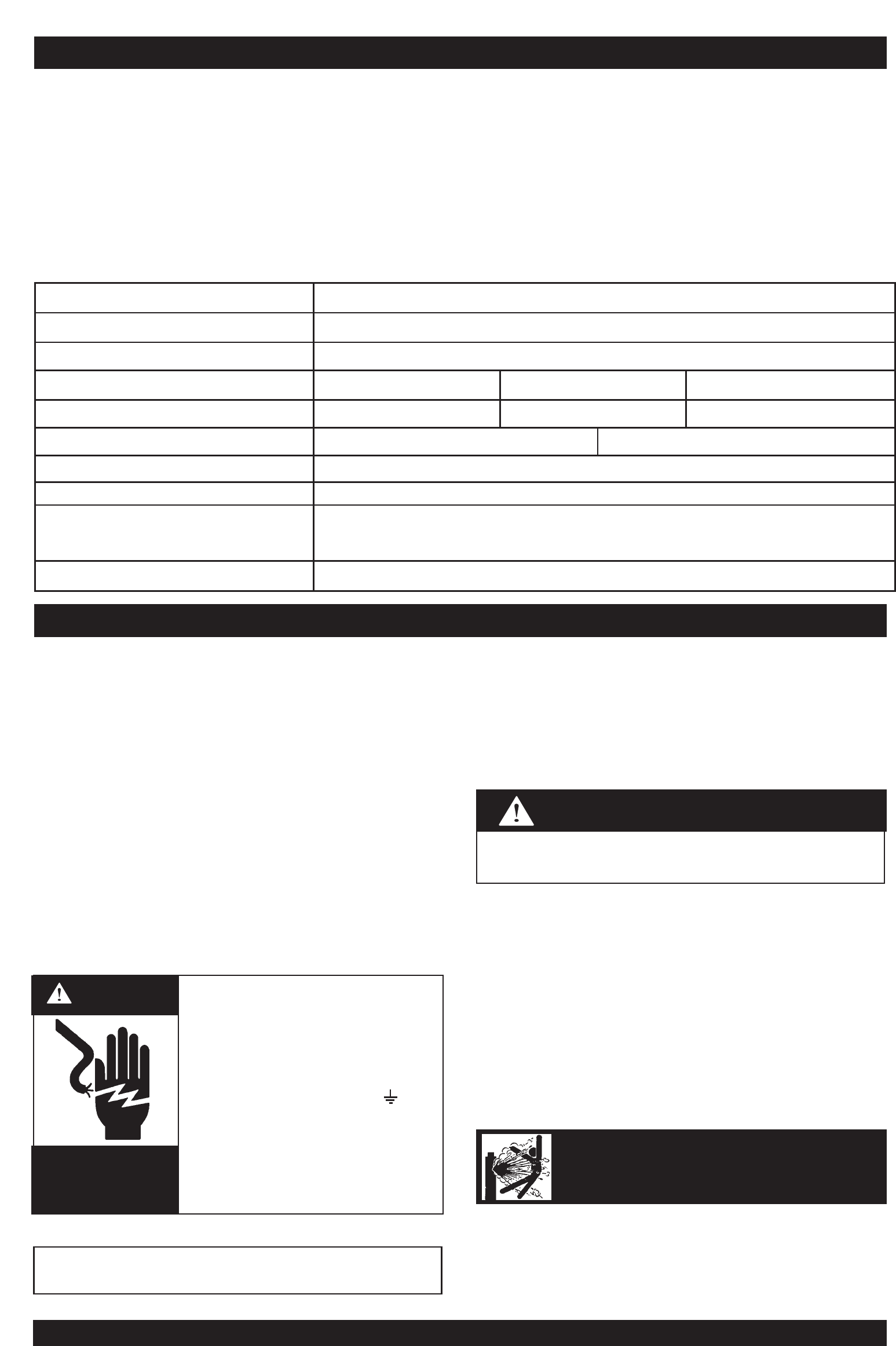
• Turn the input power off at the
disconnect switch before installing
or servicing this machine.
• Do not touch electrically “hot” parts
such as output terminals or internal
wiring.
• Connect grounding screw ( ) to a
good earth ground.
• Do not operate with covers removed.
• Turn power switch “off” before
connecting or disconnecting cables
or other equipment.
WARNING
HIGH
VOLTAGE
can kill
Page 6 CV320-I IMA 574B
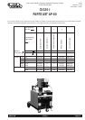
PRODUCT DESCRIPTION
The CV320-I is a semi-automatic Constant Voltage DC arc welding power source and wire feeder. It combines a step controlled power
source with a separate solid state controlled wire feeder.
Excellent arc characteristics are provided for both gas shielded and self shielded welding within its current range.
For instructions on operation of the wire feeder refer to the separate instruction manual included. Standard features include output volt &
amp meters, a spot timer, gas purge facilities, a dual position 2 or 4 step trigger interlock, a Magnum FM400 gun, a regulator/flowmeter
and gas hose, a 10m electrode cable and wire feeder cable, a 3m ground cable assembly, a 3m long input lead and an undercarriage on
which a gas cylinder can be mounted.
Only qualified personnel should install or service this
equipment.
Location
Place the welder where clean cooling air can freely circulate in
through the intake louvers and out through the exhaust louvers.
Dirt, dust or any foreign material that can be drawn into the welder
should be kept at a minimum. Failure to observe these
precautions can result in excessive operating temperatures and
nuisance thermostat trips.
Wire Feeder Mounting
Locate the control cable at the rear of the CV320-I and plug into
the wire feeder. The control cable is already connected to the
CV320-I. Connect the supplied 1.5m electrode cable to the wire
feeder mechconnector and to the desired polarity terminal on the
front of the CV320-I.
Connection to Mains Supply
Before connecting the machine to the mains supply check that the
voltage and current capacity correspond to the machine voltage
and rated input current. Use a fuse or C/B per AS3000 or local
wiring rules.
The machine is supplied with an input lead fitted. Have a qualified
electrician fit a suitable input plug.
Once the above has been followed the machine can be plugged
into the mains outlet.
Shielding Gas Supply
(For the Gas Metal Arc Welding Process)
Refer “Safety in Welding and Cutting” - ANSI Standard Z49.1 and
WTIA Technical Note 7, available from the Welding Technology
Institute of Australia.
Obtain cylinder of appropriate type shielding gas for the process
being used.
1. Set gas cylinder on rear platform of the machine. Hook chain
in place to secure cylinder to rear of welder.
2. Remove the cylinder cap. Inspect the cylinder valve for
damaged threads, dirt and dust. For cylinders having an
external thread fitting, remove any dust and dirt from the
threads with a clean cloth.
CYLINDER may explode
if damaged
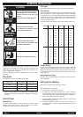
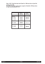
Part No. KA 1392 & KA1392-1
Maximum Open Circuit Voltage 45V
Output Current Range 20 to 400A
Duty Cycle 30% 60% 100%
Rated Output 320A/30V 240A/26V 190A/23.5V
Rated Input KA1392 415V 3ph 50Hz 13.5 amps KA1392-1 380V 3ph 50hz 14.7amps
Wire Speed Range 1-20 m/min
Weight (complete with u/c) 140 kg
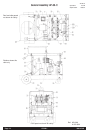
H x W x L (mm) Over wire feeder,
cylinder tray & wheels
1220 x 580 x 842 mm
Operating Temperature -20˚C to 40˚C
Specifications
INSTALLATION
Never connect the green/yellow conductor to any of the
three active supply lines from the mains. This conductor is
to earth the machine as required by Electrical Regulations.
CAUTION