


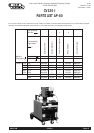

Page 8 CV320-I IMA 574B
IMPORTANT SAFETY NOTE: In 2T mode, this DC Constant
Voltage wire welder provides “COLD” electrode when the gun
trigger is not operated. Conversely, the output terminals are
“LIVE” when the gun trigger is “activated” when pressed in 2T
mode, or triggered on in 4T mode.
Refer to wire feeder manual for a description of the 2T/4T trigger
operation.
Duty Cycle
The machine is rated at the following duty cycles:
* Based on 10 min. time period (i.e., for 60% duty cycle, it is 6
minutes actual welding and 4 minutes with no welding output,
but with the input power remaining on keeping the cooling fans
operative.)
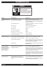
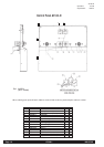
Control Panel
Power Switch
The mains power switch is incorporated in the “coarse” output
voltage control rotary switch. In the “0” position (fully counter
clockwise) the input mains power is switched off.
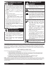
ARC RAYS
can burn
Pilot Light
This light illuminates when the input mains power is switched on
Volts Control
The output voltage is controlled by two rotary switches. One rotary
switch provides four “coarse” voltage settings as well as switching
the mains power on. The other rotary switch provides the user with
a selection of eight “fine” voltage settings. The selection between
these two rotary switches allows the user to select any one of
thirty-two welding voltages.
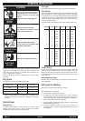
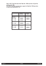
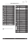
The approximate weld voltages for the rotary switch positions are:
Current Control
Use the wire feed speed control on the wire feeder to adjust the
speed at which the electrode wire feeds when welding. This is in
effect a current control as the power source will deliver the current
necessary to melt the wire. The higher the speed, the more current
will be required.
Over temperature light
Indicates that the thermostats have operated to protect unit from
over temperature.
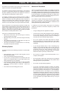
Setting Up for Welding
(Also refer to the wire feeder instruction manual.)
The following items are required:
1) A reel of wire of suitable size and type .
2) A suitable gun and cable assembly with a “Euro” connector
and the correct tip and, if necessary gas nozzle for the
consumable being used. (A Magnum FM400 gun is supplied).
3) A work return cable and clamp. (supplied)
4) Normal welding accessories including helmet or hand shield
with suitable lens, gloves etc.
5) If a gas shielded process is to be used, a cylinder of
appropriate gas is required. (Regulator/flowmeter and hose
are supplied.)
Coarse Fine Volts Coarse Fine Volts
1 1 13.0 2 1 18.0
1 2 14.0 2 2 18.5
1 3 15.0 2 3 19.0
1 4 16.0 2 4 19.5
1 5 16.5 2 5 20.0
1 6 17.0 2 6 20.5
1 7 17.5 2 7 21.0
1 8 18.0 2 8 21.5
3 1 21.5 4 1 25.0
3 2 22.0 4 2 25.5
3 3 22.5 4 3 26.0
3 4 23.0 4 4 26.5
3 5 23.5 4 5 27.0
3 6 24.0 4 6 28.0
3 7 24.5 4 7 29.0
3 8 25.0 4 8 30.0
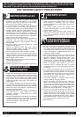
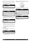
WARNING
ELECTRIC
SHOCK
can kill
FUMES AND
GASES can be
dangerous
WELDING SPARKS
can cause fire or
explosion
• Do not touch electrically live parts or
electrode with skin or wet clothing.
• Insulate yourself from work and
ground.
• Always wear dry insulating gloves.
• Keep your head out of fumes.
• Use ventilation or exhaust to remove
fumes from breathing zone.
• Keep flammable material away.
• Do not weld upon containers which
have held combustibles.
• Wear eye, ear and body protection.
Duty Cycle* Output Amps Arc Volts
30% 320 30
60% 240 26
100% 190 23.5
OPERATING INSTRUCTIONS