


!&+,$$,!'&
$&(*'
A
A
B
B
K
K
H
H
N
N
L
L
C
C
D
D
M
M
G
G
F
F
E
E
J
J
I
I
A
A
B
B
K
K
H
H
N
N
L
L
C
C
D
D
M
M
G
G
F
F
E
E
J
J
I
I
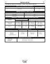
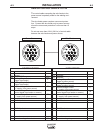
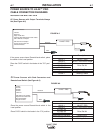
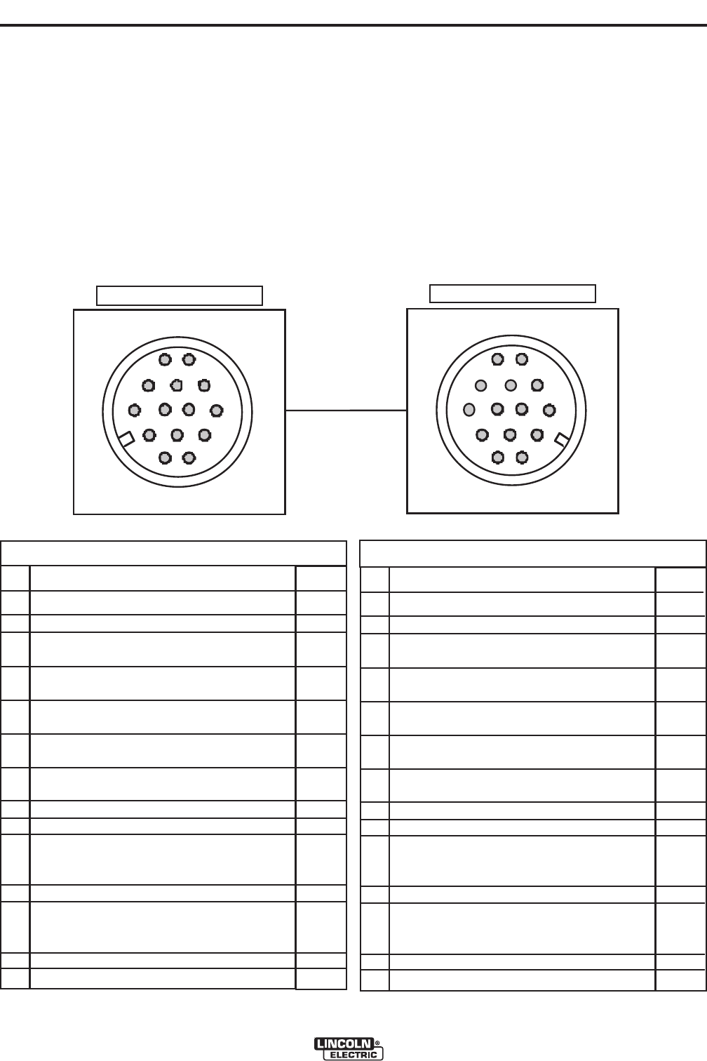
HA6G<BA
unused
Chassis GND
Welding Output Control
(trigger from feeder)
Welding Output Control
(trigger from feeder)
Remote Voltage Control
("+" supply, from power source)
Remote Voltage Control
(control signal from feeder or remote.)
Remote Voltage Control
("-" supply, from power source)
Work connection to feeder
42 VAC to feeder
Reserved
42 VAC to feeder
Reserved
unused
Electrode voltage from feeder
(<A
A
B
C
D
E
F
G
H
I
J
K
L
M
N
$847
--
GND
2
4
77
76
75
21
41
42
67
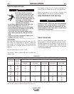
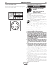
&$''&,*'$$#00
T
he control cable connecting the wire feeder to the
power source is specially made for the welding envi-
ronment.
The wire feeder power requires overcurrent protec-
tion. Connect the wire feeder only to power sources
where the overcurrent protection is no more than 15
amps.
Do not use more than 100 ft. (30.5 m) of control cable
between the wire feeder and power source.
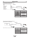
HA6G<BA
Reserved
Reserved
Welding Output Control
(trigger to power source)
Welding Output Control
(trigger to power source)
Remote Voltage Control
("+" supply, from power source)
Remote Voltage Control
(control signal from feeder or remote.)
Remote Voltage Control
("-" supply, from power source)
Work connection from power source
42 VAC to feeder
Reserved
42 VAC to feeder
Reserved
unused
Electrode voltage to power source
(<A
A
B
C
D
E
F
G
H
I
J
K
L
M
N
$847
--
2
4
77
76
75
21
41
42
67
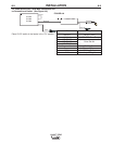
(BJ8E+BHE68
('/*+'-*
/!**
/<E88878E