


++'*!+
$&T(*'
!&+,$$,!'& ' , # /,*
''$!&#!,
$,*!+ '#64A><??
S,HEAG;8<ACHGCBJ8E'4GG;87<F
6BAA86G FJ<G6; 589BE8 JBE><A: BA
G;<F8DH<C@8AG
SBABGGBH6;8?86GE<64??L;BGC4EGF
S'A?L DH4?<9<87 C8EFBAA8? F;BH?7
<AFG4??HF8BEF8EI<68G;<F8DH<C@8AG
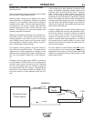
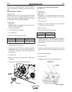
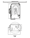
The K590-6 components are rated up to 70 psi (5 bar)
and 158°F (70°C). Use a coolant fluid that is compati-
ble with the water cooler and the gun.
Tools required:
• 3/8" wrench
• 5/16" nut driver
• medium flat bladed screw driver
• cutting tool
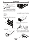
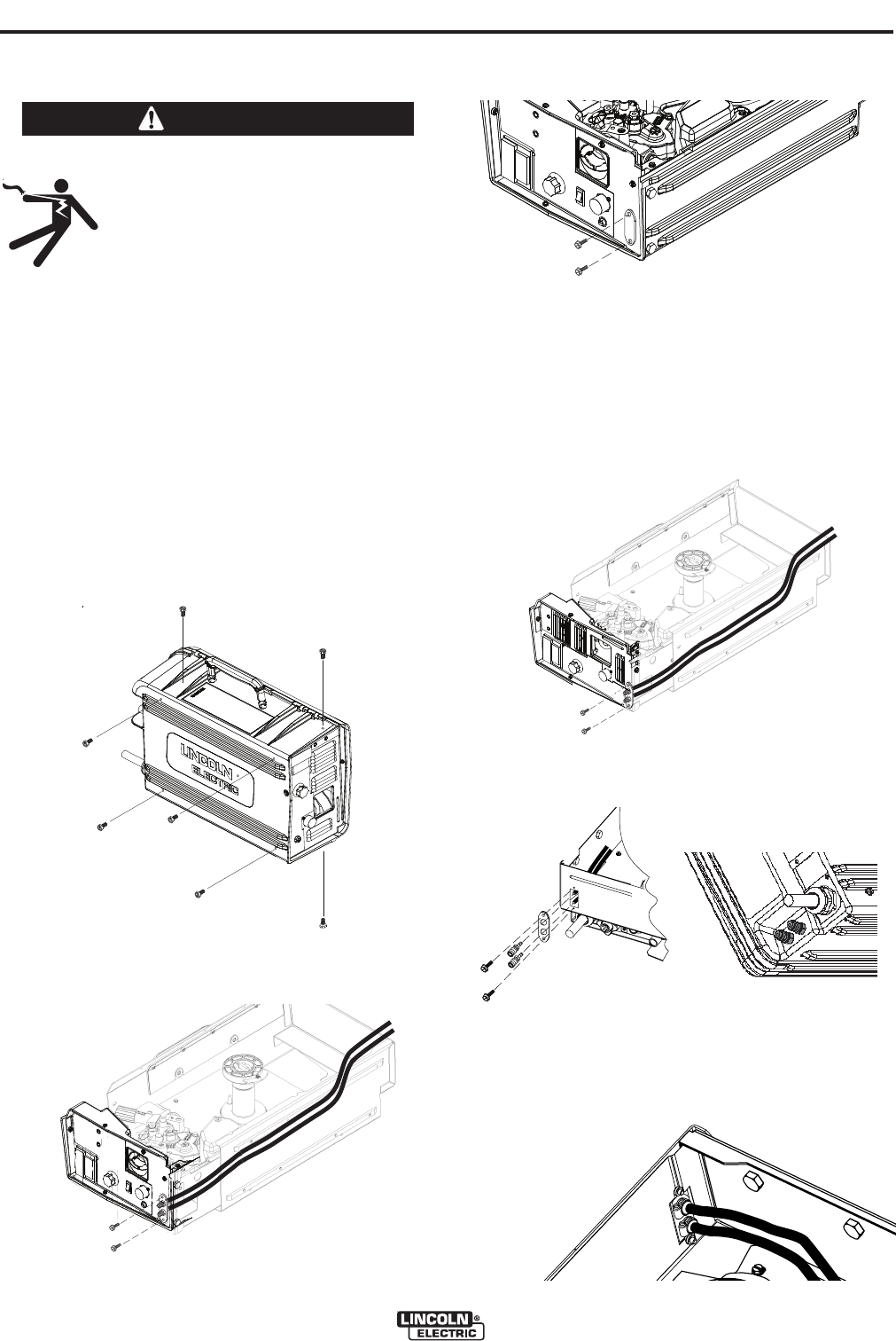
1. Turn power off at the welding power source.
2. Remove the screws securing the case to the inner
module using a 3/8" wrench.
3. Remove the module from the case by lifting the
front of the module approximately .25" (6 mm) and
then sliding forward.
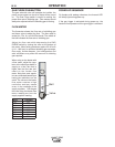
4. Use a 5/16" nut driver to remove the screws holding
the water cooling cover on the case front of the
inner module and on the rear of the case.
5. Install the fitting and hose assembly to the case
front. Route the hoses along the bottom of the
inner module and out through the cutout of the
cover. Slide the module back into the case.
6. Secure the module to the case with the screws.
(Shown in Step 2)
7. Install the fitting assembly to the rear of the case
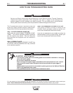
8. Slide the hose clamps on to the hoses. Trim the
hoses to length so that they lay flat on the case bot-
tom. Slide hose clamps on the hose. Slide the
hoses on to the fittings on the case rear and secure
with the hose clamps.
/*&!&
jj
oo
ee
w
w
aa
ss
hh
e
e
r
ree
2
2
00
0
0
11
jj
oo
e
e
ww
a
a
s
s
hh
e
e
r
r
ee
22
00
0
0
11
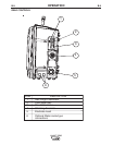
ALUMINUM CASE
PLASTIC CASE