


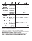

$,*!+ '#64A><??
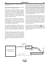
S,HEAG;8<ACHGCBJ8E'4GG;8
J8?7<A: CBJ8EFBHE68 589BE8
<AFG4??4G<BABE6;4A:<A: 7E<I8
EB??F4A7BE:H<78F
S B ABGGBH6;8?86GE<64??L ?<I8
C4EGF
S/;8A <A6;<A:J<G; G;8:HA GE<::8E8?86GEB78
4A77E<I8 @86;4A<F@4E8;BGGBJBE>4A7
:EBHA74A76BH?7 E8@4<A8A8E:<M87F8I8E4?
F86BA7F49G8EG;8:HAGE<::8E<FE8?84F87
SB ABGBC8E4G8 J<G;6BI8EF C4A8?FBE :H4E7F
E8@BI87BEBC8A
S'A?LDH4?<9<87C8EFBAA8? F;BH?7C8E9BE@@4<A
G8A4A68JBE>
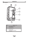
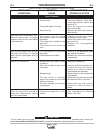
%!&,&&
$&T(*'
/*&!&
+,1(*-,!'&+
*'-,!&%!&,&&
• Check weld cables, control cables and gas hoses
for cuts.
• Clean and tighten all weld terminals.
(*!'!%!&,&&
• Clean drive rolls and inner wire guide and replace if
worn.
• Blow out or vacuum the inside of the feeder.
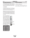
$!*,!'&+(!!,!'&
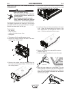
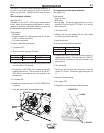
.B?G@8G8E.4?<74G<BA6EBFFG;8E6A4?B:%8G8E
%B78?F
Tools required:
• DC voltmeter reference standard
• Constant voltage DC welding power source with
adjustable no-load voltage (DC-400, V-350, CV-400
or equivalent).
To verify the analog voltmeter accuracy:
1. Turn power OFF.
2. Connect the LN-25™ PRO to the constant voltage
DC welding power source. The work lead of the
LN-25™ PRO must be connected to the work ter-
minal of the power source.
3. Connect the reference voltmeter between the
brass block of the LN-25™ PRO and the work
lead.
4. Turn power ON.
5. Energize the output circuit of the power source.
Adjust the power source output to 20±1 VDC as
measured on the reference meter.
6. Verify that LN-25™ PRO voltmeter reads between
19 and 21 volts.
If the voltmeter reading is out of range, check for
loose connections or replace the voltmeter. There is
no calibration adjustment for the LN-25™ PRO volt-
meter.
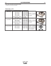
?BJ%8G8E.4?<74G<BA
Tools required:
• Flow meter reference standard.
• Constant voltage DC welding power source (DC-
400, V-350, CV-400 or equivalent).
To verify the flow meter accuracy:
1. Turn power OFF.
2. Connect the LN-25™ PRO to the constant voltage
DC welding power source. The work lead of the
LN-25™ PRO must be connected to the work ter-
minal of the power source.
3. Connect a supply of CO2 to the wire feeder. Do
not exceed the maximum inlet pressure of the wire
feeder.
4. Disconnect the shielding gas hose that connects to
the gun bushing.
5. Connect the shielding gas hose to flow meter refer-
ence standard.
6. Orient the LN-25™ PRO in a vertical position.
7. Turn power ON.
8. Adjust the flow meter on the LN-25™ PRO to 40
scfh while pressing the GAS PURGE button.
9. Measure the gas flow with the calibrated flow
meter while pressing the GAS PURGE button.
10. The measured flow rate should be between 35
and 45 scfh.