


/!**!.'&!-*,!'&
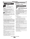
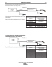
(See Figure A.2)
-&-+ !& , -% +*/&
+'#, (+*/
$,*!+ '#64A><??
S,HEAG;8<ACHGCBJ8E'4GG;8
J8?7<A:CBJ8EFBHE68589BE8<AFG4?
?4G<BABE6;4A:<A:7E<I8EB??F4A7BE
:H<78F
SBABGGBH6;8?86GE<64??L?<I8C4EGF
S/;8A<A6;<A:J<G;G;8:HAGE<::8E8?86GEB78
4A77E<I8@86;4A<F@4E8;BGGBJBE>4A7
:EBHA74A76BH?7E8@4<A8A8E:<M87F8I8E4?F86
BA7F49G8EG;8:HAGE<::8E<FE8?84F87
SBABGBC8E4G8J<G;6BI8EFC4A8?FBE:H4E7F
E8@BI87BEBC8A
S'A?LDH4?<9<87C8EFBAA8?F;BH?7C8E9BE@@4<AG8
A4A68JBE>
------------------------------------------------------------------------
Tools required:
• 1/4" hex key wrench.
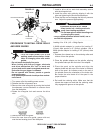
Note: Some gun bushings do not require the use of
the thumb screw.
1. Turn power off at the welding power source.
2. Remove the welding wire from the wire drive.
3. Remove the thumb screw from the wire drive.
4. Remove the welding gun from the wire drive.
5. Loosen the socket head cap screw that holds the
connector bar against the gun bushing.
!@CBEG4AG B ABG 4GG8@CG GB 6B@C?8G8?L
E8@BI8G;8FB6>8G;84764CF6E8J
6. Remove the outer wire guide, and push the gun
bushing out of the wire drive. Because of the pre-
cision fit, light tapping may be required to remove
the gun bushing.
7. Disconnect the shielding gas hose from the gun
bushing, if required.
8. Connect the shielding gas hose to the new gun
bushing, if required.
9. Rotate the gun bushing until the thumb screw hole
aligns with the thumb screw hole in the feed plate.
Slide the gun receiver bushing into the wire drive
and verify the thumb screw holes are aligned.
10. Tighten the socket head cap screw 10 to 14 ft-lbs
(13.5 to 19.0 Nm).
11. Insert the welding gun into the gun bushing and
tighten the thumb screw.
/*&!&
+ !$!&+'&&,!'&
1$!&*@4L8KC?B78<9
74@4:87
S #88C6L?<A78EHCE<:;G4A7
6;4<A87GBFHCCBEG
S#88C6L?<A78E4J4L9EB@4E84FJ;8E8<G@4L58
74@4:87
S&8I8E?<9GJ8?78EJ<G;6L?<A78E4GG46;87
S&8I8E4??BJJ8?7<A:8?86GEB78GBGBH6;6L?<A78E
S#88C6L?<A78E4J4L9EB@J8?7<A:BEBG;8E?<I8
8?86GE<64?6<E6H<GF
S-!$-('+ !$!&+%1
*% $, '*#!$$
S+;HGB99F;<8?7<A::4FFHCC?LJ;8AABG
<AHF8
S+88@8E<64A&4G<BA4?+G4A74E7 2+498GL
<A/8?7<A: 4A7 HGG<A:Y (H5?<F;875L G;8
@8E<64A/8?7<A:+B6<8GL
------------------------------------------------------------------------
Maximum inlet pressure is 100 psi. (6.9 bar.)
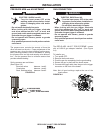
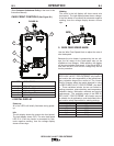
Install the shielding gas supply as follows:
1. Secure the cylinder to prevent it from falling.
2. Remove the cylinder cap. Inspect the cylinder valves
and regulator for damaged threads, dirt, dust, oil or
grease. Remove dust and dirt with a clean cloth. '
&',,, , *-$,'*!'!$*+
'*%!+(*+&,Inform your gas supplier
of this condition. Oil or grease in the presence of high
pressure oxygen is explosive.
3. Stand to one side away from the outlet and open the
cylinder valve for an instant. This blows away any dust
or dirt which may have accumulated in the valve out-
let.
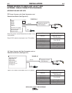
4. Attach the flow regulator to the cylinder valve and
tighten the union nut(s) securely with a wrench. Note:
if connecting to 100% CO
2
cylinder, insert regulator
adapter between regulator and cylinder valve. If
adapter is equipped with a plastic washer, be sure it is
seated for connection to the CO
2
cylinder.
5. Attach one end of the inlet hose to the outlet fitting of
the flow regulator. Attach the other end to the welding
system shielding gas inlet. Tighten the union nuts with
a wrench.
6. Before opening the cylinder valve, turn the regulator
adjusting knob counterclockwise until the adjusting
spring pressure is released.
7. Standing to one side, open the cylinder valve slowly a
fraction of a turn. When the cylinder pressure gage
stops moving, open the valve fully.
8. The flow regulator is adjustable. Adjust it to the flow
rate recommended for the procedure and process
being used before making a weld.
/*&!&
!&+,$$,!'&
**$&T(*'0,*%