


'(*,!'&
!!,$!+($1
(BJ8EHC
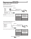
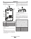
All of the LED’s will briefly illuminate during power-
up.
!7?8
The left display shows the preset wire feed speed.
The right display shows OCV. The wire feed speed
LED is lit. If the wire feeder is connected for elec-
trode negative welding, then the voltage display
shows a minus sign.
(See HFGB@8EFF<FG4A68(B?<6L in the front of this
Instruction Manual)
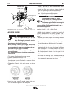
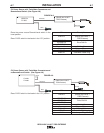
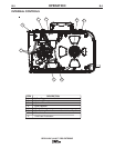
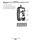
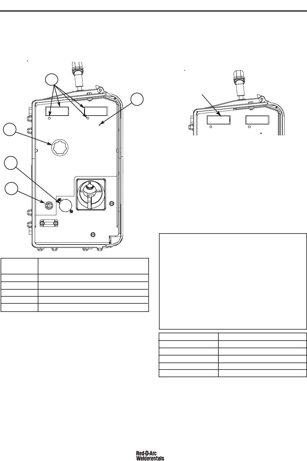
+*'&,'&,*'$+ +88<:HE8
!,%+*!(,!'&
1 Digital Display
2 Wire Feed Speed Knob
3 5-pin gun trigger connector
4 Work sense lead
5 Set-up Pushbutton
**$&T(*'0,*%
150
WFS
150
WFS
1
5
2
3
4
!-*
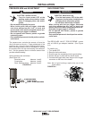
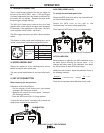
/8?7<A:
The value in the left display will show actual wire
feed speed. The right display shows the arc voltage.
If the wire feeder is connected for electrode negative
welding, then the voltage display shows a minus
sign.
/!*+(#&'
Use the Wire Feed Speed Knob to adjust the rate of
wire feed speed.
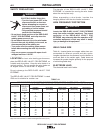
Because the wire feeder is powered by the arc volt-
age, the full range of wire feed speed may not be
available at low voltages. While welding, the display
will show actual wire feed speed. If the actual WFS is
less than set WFS, then the arc voltage may be too
low for procedure.
Arc Voltage
Max WFS (Inches Per Minute)
15V 400ipm
17V 450ipm
21V 570ipm
24V 650ipm
27V 700ipm
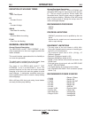
The serviceability of a product or structure utilizing the
RED-D-ARC LN-25™ PRO EXTREME wire feeder is
and must be the sole responsibility of the builder/user.
Many variables beyond the control of The Lincoln
Electric Company affect the results obtained in using
the RED-D-ARC LN-25™ PRO EXTREME wire feed-
er. These variables include, but are not limited to,
welding procedure, plate chemistry and temperature,
weldment design, fabrication methods and service
requirements. The available range of the RED-D-
ARC LN-25™ PRO EXTREME wire feeder may not
be suitable for all applications, and the builder/user is
and must be solely responsible for welding settings.