


!&+,$$,!'&
**$&T(*'0,*%
$'!&+(''$+'/!*
S#88C;4A7F;4<E6?BG;<A:4A7GBB?F
4J4L9EB@EBG4G<A:8DH<C@8AG
SBABGJ84E:?BI8FJ;8AG;E847<A:J<E8
BE6;4A:<A:J<E8FCBB?
S'A?LDH4?<9<87C8EFBAA8?F;BH?7<AFG4??HF8BE
F8EI<68G;<F8DH<C@8AG
------------------------------------------------------------------------
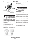
Loading 10 to 15 lb. (4.5 – 6.8kg) Spools.
A K468 spindle adapter is required for loading 2"
(51mm) wide spools on 2" (51mm) spindles. Use a
K468 spindle adapter for loading 2-1/2" (64mm) wide
spools.
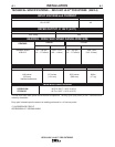
/*&!&
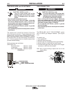
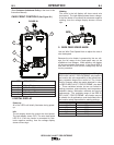
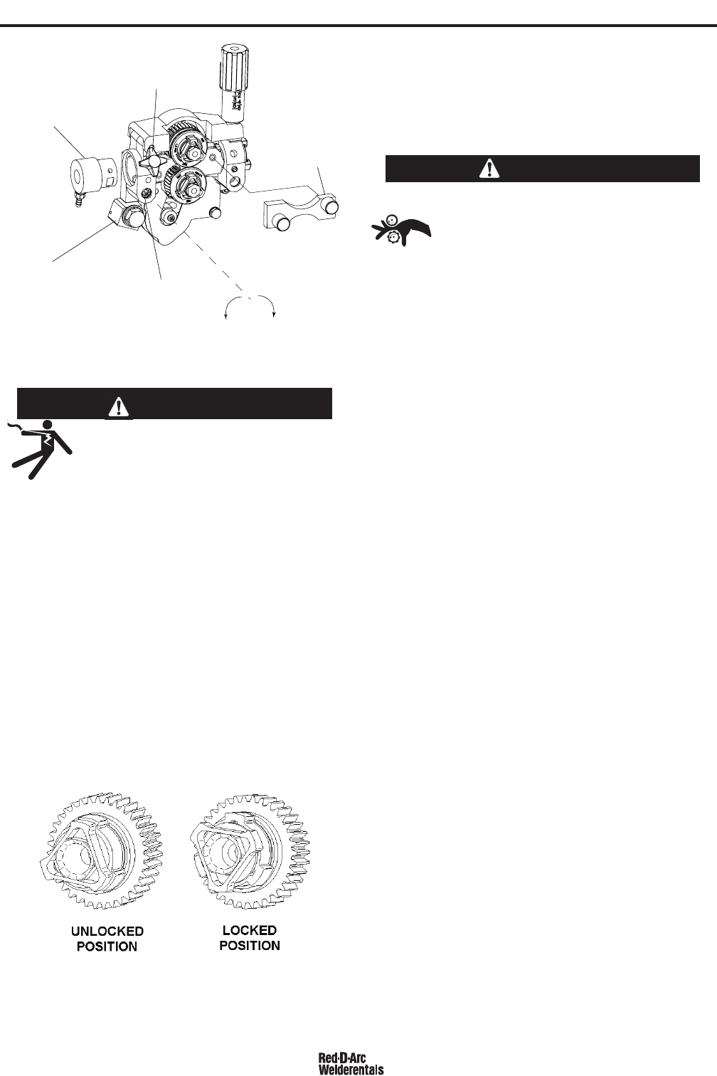
GUN RECEIVER BUSHING
LOOSEN TIGHTEN
THUMB SCREW
OUTER WIRE GUIDE
SOCKET HEAD
CAP SCREW
CONNECTOR BLOCK
GUN RECEIVER BUSHING
LOOSEN TIGHTEN
THUMB SCREW
OUTER WIRE GUIDE
SOCKET HEAD
CAP SCREW
CONNECTOR BLOCK
(*'-*,'!&+,$$*!.*'$$+
&/!*-!+
S ,HEAG;8<ACHGCBJ8E'4GG;8
J8?7<A:CBJ8EFBHE68589BE8<AFG4?
?4G<BABE6;4A:<A:7E<I8EB??F4A7BE
:H<78F
SBABGGBH6;8?86GE<64??L?<I8C4EGF
S/;8A<A6;<A:J<G;G;8:HAGE<::8E8?86GEB78
4A77E<I8@86;4A<F@4E8;BGGBJBE>4A7
:EBHA74A76BH?7E8@4<A8A8E:<M87F8I8E4?F86
BA7F49G8EG;8:HAGE<::8E<FE8?84F87
SBABGBC8E4G8J<G;6BI8EFC4A8?FBE:H4E7F
E8@BI87BEBC8A
S'A?LDH4?<9<87C8EFBAA8?F;BH?7C8E9BE@@4<AG8
A4A68JBE>
------------------------------------------------------------------------
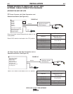
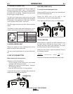
1. Turn power off at the welding power source.
2. Release the idle roll pressure arm.
3. Remove the outer wire guide by turning the knurled
thumbscrews counter-clockwise to unscrew them
from the feed plate.
4. Rotate the triangular lock and remove the drive
rolls.
5. Remove the inner wire guide.
6. Insert the new inner wire guide, groove side out,
over the two locating pins in the feed plate.
/*&!&
!-*
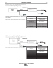
7. Install a drive roll on each hub assembly secure
with the triangular lock.
8. Install the outer wire guide by aligning it with the
pins and tightening the knurled thumbscrews.
9. Close the idle arm and engage the idle roll pressure
arm. Adjust the pressure appropriately.
1. Squeeze the release bar on the retaining collar and
remove it from the spindle.
2. Place the spindle adapter on the spindle, aligning
the spindle brake pin with the hole in the adapter.
3. Place the spool on the spindle and align the
adapter brake tab with one of the holes in the back
side of the spool. An indicator mark on the end of
the spindle shows the orientation of the brake tab.
Be certain the wire feeds off of the spool in the
proper direction.
4. Re-install the retaining collar. Make sure that the
release bar snaps out and that the retaining collar
fully engages the groove on the spindle.