


C-2
MAINTENANCE
C-2
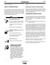
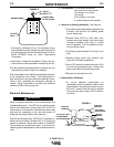
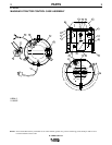
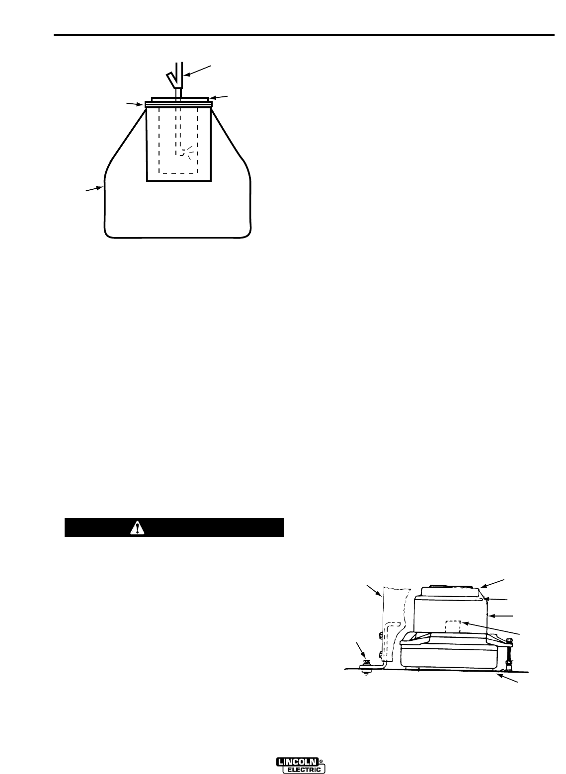
*If air supply is limited to 30 psi, use a booster air gun
that increases dynamic pressure and still retains a 30
psi static pressure such as Guardair Booster Air Gun,
Model 57530XB made by Union Engineering
Corporation.
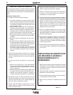
4.After Step 3, repeat the procedure in Step 2 for sev-
eral minutes to remove material loosened by the air.
5.All the material removed should be carefully put into
the plastic bag used in Step 3 for disposal.
With reasonable care in handling, these filters can eas-
ily be reused five or six times. The limiting factor in
their service life is the point where the element is frac-
tured or torn, permitting the continuous passage of
smoke. Using a fractured or torn filter may seriously
shorten the life of the vacuum unit.
Electrical Maintenance
Have a qualified electrician do the maintenance and
troubleshooting work. Turn OFF the arc welding power
source and disconnect control leads #31 and #4 at
power source or wire feeder. Remove the power cable
plug from its receptacle or turn the input power off
using the disconnect switch at the fuse box.
------------------------------------------------------------------------
Check motor brushes after 1,000 hours of operation or
about every six months. Brushes worn to 1/4 inch long
should be replaced. Brush part number is S14688-D.
Two brushes are required per motor. Instructions for
checking and/or replacement of the brushes are as fol-
lows:
a. Tools Needed: 4" flat blade screwdriver
3/8" open end or box wrench
1/4" socket or nut driver/
1/2" socket
5/16" socket or nut driver
4" socket extension and ratchet.
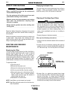
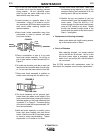
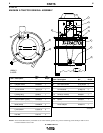
b. Removal of Housing Assembly - See Figure 4.
1.Turn off the input power being supplied to the
X-Tractor unit and the arc welding power
source being used.
2.Remove three 5/16"-18 x 5/8" bolts, lock-
washers and plain washer that hold control
housing to canister cover using a " socket
and 4" extension. Do not remove the acorn
nuts on the top cover.
3.Lift housing approximately 6" and tip to one
side.
4.Remove motor leads from terminal strip
using a 4" flat blade screwdriver.
5.Use a 3/8" wrench to remove the outer 10-24
nut from the grounding screw. Remove the
green motor lead from grounding screw.
6.Remove the housing from unit.
c. Replacement of Brushes
1.To insure optimum commutation on
reassembly, mark the relative location of the
screw heads in the slots and remove the two
#10-24 x 2 screws from the top end bracket
of the vacuum motor using a 5/16" socket or
nut driver.
X-TRACTOR 1G
WARNING
RUBBER BAND
PLASTIC
BAG
80 - 100 PSI
AIR SUPPLY
GASKET END
OF AIR FILTER
FIGURE 3
*
CONTROL
HOUSING
5/16-18x5/8" BOLT,
LOCKWASHER
& PLAIN WASHER
TOP END
BRACKET
#10-24 HEX
HEAD SCREW
MOTOR
COVER
BRUSH
HOLDER
CANISTER
COVER
FIGURE 4