


C-3
MAINTENANCE
C-3
2.Lift off the top end bracket from the motor.
Be careful not to lose the bearing pre-load
spring washer. Lift the cylindrical motor
cover up from the motor, slide back on the
leads and tilt away from motor.
3.Locate brushes on opposite sides of the
commutator. Using a 1/4” socket or nut dri-
ver, remove two #8-32 hex head screws from
each brush holder retaining bracket and
remove brackets.
4.Move brush holder assemblies away from
commutator in order to remove coil leads
from brush holders.
10.Place motor cover over motor. Make sure
the bearing spring washer is on top of the
armature bearing and positioned to fit into
bearing seat in the top end bracket.
11.Position the top end bracket so the bolt
slots are directly over the threaded holes in
motor frame. Place the #10-24 x 2.0"
screws through the slots and install loosely
using a 5/16" socket or nut driver. Rotate
the top end bracket to align heads of the
screws with the marks at the slots made in
Step c.1 and tighten.
d. Replacement of Housing Assembly
Attach motor leads and install housing assem-
bly in the reverse order of Step b.
e. Run-in of Brushes
After replacing brushes, run smoke exhaust
unit on low idle for 30 minutes. Unit is on low
idle when power cable is energized, power
switch is on, and control (#31 and #4) cable is
not connected.
See S17238 included with replacement motor for
instructions for complete vacuum motor replacement.
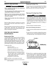
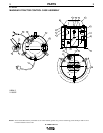
X-TRACTOR 1G
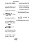
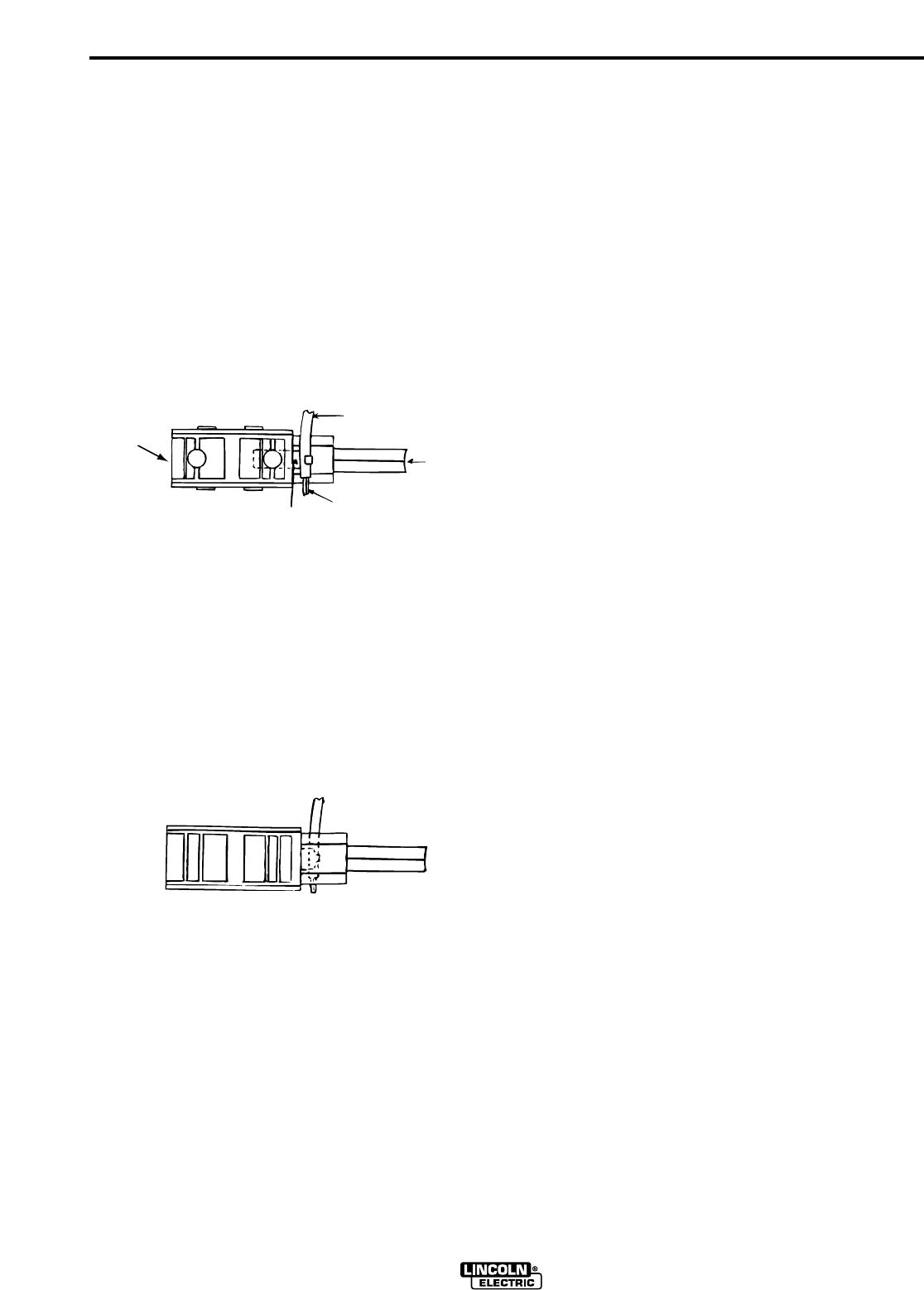
TOP VIEW
BRUSH
HOLDER
COIL
LEAD
BRUSHES
A
B
FIGURE 5
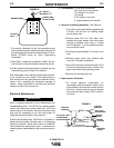
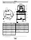
BOTTOM VIEW
C
FIGURE 6
5.Place a screwdriver in area A to pry lead
from brush holder assembly. Do not pry or
pull on bare section of lead denoted by B in
Figure 5.
6.To install new brushes, push tab on each coil
lead into the slot on either side of brush hold-
er. Do not bend the bare section of lead (B).
7.Place each brush assembly in position on
bottom motor housing with coil lead on top.
8.The brush assembly will be properly posi-
tioned when the raised round locater in the
brush area of the bottom housing fits into the
indented section on the brush assembly that
is marked "C" in Figure 6. The brass portion
of the brush holder will be approximately 1/8"
from the commutator.
9.With the brush assembly in position, place
brush hold down bracket over each brush
holder. Start the four #8-32 hex head screws
by hand to avoid cross-threading. Tighten
screws with a 1/4” socket or nut driver.