


Work Cable Installation
1. Open the wire feed section door on the right side of
the SP-100.
2. Pass the end of the work cable that has the termi-
nal lug with the smaller hole through the hole (hole
D) next to the louvers in the case front.
3. Route the cable under and around the back of the
wire feed unit.
4. Using wing nut provided, connect the terminal lug
to the negative (–) output terminal located above
the wire feed unit; item M (make certain that
both
wing nuts are tight).
NOTE: This connection gives the correct electrode
polarity for the GMAW process. If using Innershield,
see Output Polarity Connection Section below for
negative electrode polarity connection.
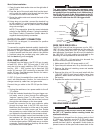
OUTPUT POLARITY CONNECTION
The SP-100, as shipped, is connected for positive
electrode polarity.
To connect for negative electrode polarity (required for
the Innershield process), connect the short cable
attached to the gun connector block to the negative
(–) output terminal and the work cable to the positive
(+) terminal using the provided wing nuts (make cer-
tain that both wing nuts are tight).
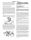
GUN INSTALLATION
As shipped from the factory, the SP-100 gun is ready
to feed .023, .024 or .025" (0.6 mm) wire. If .030" (0.8
mm) wire is to be used, install the .030" (0.8 mm) con-
tact tip. .023 – .025" contact tip is stenciled .025
and/or 0.6 mm and .030" contact tip is stenciled .030
and/or 0.8 mm. See Maintenance Section for instruc-
tions to change contact tip.
If .035" (0.9 mm) Innershield flux cored wire is to be
used, see Maintenance Section for instructions to
change contact tip, cable liner, and gas nozzle.
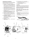
Connect the gun cable to the SP-100 per the follow-
ing:
1. Unplug the machine or turn power switch to the off
“O” position.
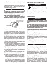
2. Pass the insulated terminals of the gun trigger con-
trol leads, one at a time, through the rectangular
“keyhole” opening (item F) in the case front. The
leads are to be routed under the wire feed unit and
through the cable hanger on the inner panel.
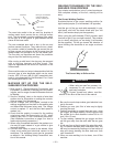
3. Insert the connector on the gun conductor cable
through the large hole in the SP-100 case front.
Make sure the connector is all the way in the metal
connector block to obtain proper gas flow. Rotate
the connector so control leads are on the underside
and tighten the thumbscrew in the connector block.
4. Connect the insulated control lead terminals to the
two insulated 1/4" (6.4 mm) tab connector bushings
located above the “Gun Trigger Connection” decal
in the wire feed section. Either lead can go to either
connector. Form the leads so that they are as close
as possible to the inside panel.
– 10 –
The gun trigger switch must be a normally open,
momentary switch. The terminals of the switch must
be insulated from the welding circuit. Malfunction of
the SP-100 will result if this switch shorts to the SP-
100 welding output circuit or is common to any elec-
trical circuit other than the SP-100 trigger circuit.
-----------------------------------------------------------------------
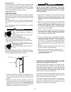
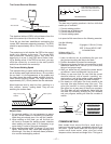
WIRE FEED DRIVE ROLL
The SP-100 drive roll has two grooves; one for .023 –
.025" (0.6 mm) solid steel electrode and the other for
.030" (0.8 mm) solid and .035" (0.9 mm) flux-cored
steel electrode. As shipped, the drive roll is installed in
the .023/.025" (0.6 mm) position (as indicated by the
stenciling on the exposed side of the drive roll).
If .030 – .035" (0.8 – 0.9 mm) wire is to be used, the
drive roll must be reversed as follows:
1. Make certain the SP-100 power switch is “off”.
2. Open the quick release arm; lift up the idle roll arm.
3. Remove the drive roll retaining screw and washer
with a screwdriver.
4. Remove the drive roll, flip over and install with the
.030/.035" (0.8/0.9 mm) stencil visible (away from
gearbox). Make certain the small key is in place in
the keyway.
5. Replace the washer and retaining screw.
Gun trigger
connectors
Thumbscrew
Case front
Gun connector block
{
Brass connector
Gun trigger
control lead
terminals
Idle roll arm
Retaining Screw
Drive roll
Spring loaded
pressure arm
CAUTION
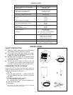
WELDING WIRE LOADING
The machine power switch should be turned to
the OFF (“O”) position before working inside the
wirefeed enclosure.
------------------------------------------------------------------------
The machine is shipped from the factory ready to feed
8" (200 mm) diameter spools [2.2" (56 mm) max.
width]. These spools fit on a 2" (50 mm) diameter
spindle that has a built-in, adjustable* friction brake to
prevent overrun of the spool and excess slack in the
WARNING