


ELECTRICAL INPUT CONNECTION
Code Requirements
This welding machine must be connected to power
source in accordance with applicable electrical
codes.
The United States National Electrical Code (Article
630-B, 1990 Edition) provides standards for amper-
age handling capability of supply conductors based
on duty cycle of the welding power source.
If there is any question about the installation meeting
applicable electrical code requirements, consult a
qualified electrician.
------------------------------------------------------------------------
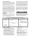
Requirements for Rated Output
A power cord with a 15 amp, 125 volt, three prong
plug (NEMA Type 5-15P) is factory installed on the
SP-100. Connect this plug to a mating grounded
receptacle which is connected to a 20 amp branch cir-
cuit with a nominal voltage rating of 115 to 125 volts,
60 Hertz, AC only.
The rated output with this installation is 90 amps, 18
volts, 20% duty cycle (2 minutes of every 10 minutes
used for welding).
Do not connect the SP-100 to an input power supply
with a rated voltage that is greater than 125 volts.
-------------------------------------------------------------------------------------------------------
Requirements for Maximum Output
An optional power cord is available to permit the SP-
100 to be connected to a 25 amp branch circuit with a
nominal voltage rating of 115 to 125 volts, 60 Hertz,
AC only. With this installation the SP-100 can be used
at an output of 100 amps, 17 volts, 30% duty cycle.
See Optional Accessories Section.
Requirements for CSA Rated Output
A line cord with a 15 amp, 125 volt, three-prong plug
(NEMA Type 5-15P) is factory installed. Connect this
plug to a mating grounded receptacle which is con-
nected to a 15 amp branch circuit with a nominal volt-
age rating of 115 volts to 125 volts, 60 hertz, AC only.
With this installation, the SP-100 can be used at an
output of 63 amps, 20 volts, 20% duty cycle.
– 11 –
wire. The thumb screw at the end of the shaft is not
intended to be loosened; it should be tightened full
clockwise.
*Earlier spindle shafts did not include a set screw to
adjust brake friction. If set screw is desired, order
Lincoln part number T12932-2.
If full tightening of the spindle thumbscrew causes
too much feed force to rotate the wire spool, the
thumbscrew stop point can be adjusted as follows:
A. Remove the thumbscrew.
B. Using a 3/16”(4.8mm) hex wrench, turn the set
screw, located inside the tapped hole in the spindle
shaft, one or two turns counterclockwise.
C. Fully reinstall the thumbscrew and check for
proper brake force to prevent spool overrun, but
allow smooth and easy wire feeding. If not, repeat.
------------------------------------------------------------------------
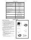
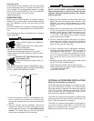
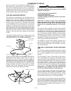
Load an 8" (200 mm) diameter spool on the wire spool
spindle shown above.
To use 4" (100 mm) diameter spools, the 2" (50 mm)
diameter spindle must be removed. Remove the
thumb screw at the end of the shaft and remove the
spindle. It can be stored in the wire feed compartment.
A 4" (100 mm) diameter spool is mounted directly on
the 5/8" (16 mm) diameter shaft and held in place with
the previously removed thumb screw. Make certain
that the thumbscrew is tightened fully clockwise. Also
make certain the start end of the wire which may pro-
trude through the side of the spool does not contact
any metallic case parts.
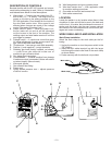
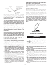
Thread the welding wire through the wire feeder guide
tubes per the following instructions:
1. Release the idle roll pressure arm and rotate the
idle roll arm away from the drive roll. (Check that
visible, stenciled size on drive roll matches wire
size being used — See Wire Drive Roll Section.)
2. Carefully detach the end of the wire from the spool.
To prevent the spool from unwinding, do
not
release the wire until after step 5.
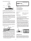
3. Cut the bent portion of wire off and straighten the
first 4" (100 mm).
4. Thread the wire through the ingoing guide tube,
over the drive roll, and into the outgoing guide tube.
5. Close the idle roll arm and latch the pressure arm in
place (now you may release the welding wire).
6.
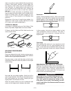
The idle roll pressure adjustment wing nut is normal-
ly set for mid-position on the pressure arm threads.
If feeding problems occur because the wire is flat-
tened excessively, turn the pressure adjustment
counterclockwise to reduce distortion of the
wire.Slightly less pressure may be required when
using .023–.025 (0.6 mm) wire. If the drive roll slips
while feeding wire, the pressure should be increased
until the wire feeds properly. NOTE: See operating
instructions for feeding welding wire on
page 12.
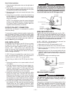
Be sure this stud engages
the hole in the wire spool
Wire spool must be pushed all
the way on spindle so the tab
springs out to hold it in place.
Spool to rotate clockwise
when wire is dereeled.
Thumbscrew
ELECTRIC SHOCK can kill.
• Disconnect input power by removing
plug from receptacle before working
inside SP-100.
• Use only grounded receptacle.
• Do not remove the power cord ground prong.
• Do not touch electrically “hot” parts inside SP-100.
• Have qualified personnel do the maintenance and
troubleshooting work.
---------------------------------------------------------------------
WARNING
WARNING
CAUTION
CAUTION