


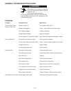

MACHINE SETUP FOR THE GMAW (MIG)
PROCESS
1. See “Recommended Processes and Equipment” for
selection of welding wire and shielding gas and for
range of metal thicknesses that can be welded.
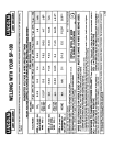
2. See the “Welding ” chart on the inside of wire feed
section door or in this manual for information on
setting the controls.
3. Set the “Voltage” and “Wire Speed” controls to the
settings suggested for the welding wire and base
metal thickness being used. The voltage control is
marked “V” and the wire feed speed is marked olo.
4. Check that the polarity is correct for the welding
wire being used. Set the polarity for DC(+) when
welding with the GMAW (MIG) process. (See page
9 of the Installation Instructions on how to make
output polarity connections.)
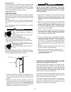
5. Check that the gas nozzle and proper size liner and
contact tip are being used, and that the gas supply
is turned on. If adjustable, set for 15 to 20 cubic
feet per hour (7 to 10 liters/min) under normal con-
ditions; increase as high as 35 CFH (17 liters/min)
under drafty (slightly windy) conditions.
NOTE: The gas regulators included in the optional
K463 and K499 kits are preset and nonadjustable.
6. Connect work clamp to metal to be welded. Work
clamp must make good electrical contact to the
workpiece. The workpiece must also be grounded
as stated in “Arc Welding Safety Precautions.”
WELDING TECHNIQUES FOR THE GMAW
(MIG) PROCESS
The welding techniques for the GMAW (MIG) process
on light gauge material are basically the same as
welding with .035" (0.9 mm) NR-211-MP Innershield
electrode. (Review welding techniques in the self-
shielded FCAW Innershield section on page 14.) The
few exceptions are noted below.
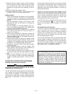
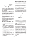
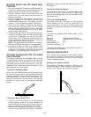
The Correct Welding Position
When using the GMAW process on light gauge mater-
ial, weld from right to left (if right handed) pushing the
electrode ahead of the arc (see figure following). This
technique results in a colder weld and has less ten-
dency for burnthrough. You may weld in the opposite
direction as long as you are obtaining desirable
results.
The Correct Way to Strike an Arc
1. The arc is struck the same as for self-shielded
FCAW welding. However, for easier restrikes, the
ball at the tip end of the wire which forms after com-
pleting a weld may be removed with wire cutters.
2. When no more welding is to be done, don’t forget to
first close valve on gas cylinder (if used), momentarily
operate gun trigger to release gas pressure, then turn off
the machine.
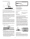
The Correct Electrical Stickout
The electrical stickout (ESO) for GMAW (MIG) weld-
ing is 3/8 to 1/2 inch (10 to 12 mm). The same rules
apply as when welding with .035" (0.9 mm) NR-211-MP
Innershield wire.
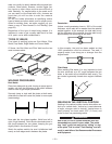
The Correct Welding Speed
The same rules apply as those for self-shielded
FCAW welding. At first, it may be more difficult to
judge speed since no slag is forming behind the
molten pool. Watch the ridge where the molten puddle
solidifies.
Practice
To practice your GMAW (MIG) welding skills, use the
following:
Mild steel 16 gauge (about 1/16 inch)
Electrode Lincolnweld
®
.025 L-56 electrode
Shielding gas CO
2
Voltage setting “V” G
Wire feed speed olo 5
Then follow the instructions in the practice section on
self-shielded FCAW welding.
WELDING PROCEDURES
When GMAW (MIG) welding on sheet metal, remem-
ber to use the “forehand” push technique, and review
the welding procedures section on self-shielded
FCAW Innershield welding.
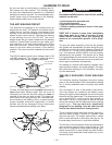
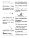
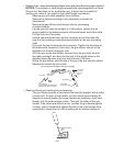
Welding in the Vertical Position
One variation of welding procedure is welding in the
vertical-up position. When welding in the vertical-up
position, use the proper gun angle shown below.
Gun angle for the GMAW process welding in the vertical-up position.
Push Technique
– 20 –