


– 19 –
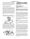
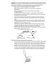
Vertical-Up and Overhead Welding
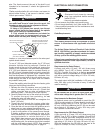
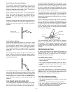
The problem, when welding vertical-up, is to put the
molten metal where it is wanted and make it stay
there. If too much molten metal is deposited, gravity
will pull it downwards and make it “drip.” Therefore, a
certain technique has to be followed.
When welding out-of-position, run stringer beads.
Don’t whip, break the arc, move out of the puddle, or
move too fast in any direction. Use WFS in the low
portion of the range. General techniques are illustrat-
ed below.
Generally, keep the electrode nearly perpendicular to
the joint as illustrated. The maximum angle above per-
pendicular may be required if porosity becomes a
problem.
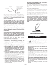
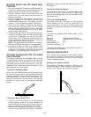
Vertical-Down Welding
Vertical-down welds are applied at a fast pace. These
welds are therefore shallow and narrow, and as such
are excellent for sheet metal. Vertical-down welds
may be applied to 5/32" (3.9 mm) and lighter material.
This material is within the range of the SP-100 when
used with .035" (0.9 mm) NR-211-MP Innershield
electrode.
Use stringer beads and tip the gun in the direction of
travel so the arc force helps hold the molten metal in
the joint. Move as fast as possible consistent with
desired bead shape.
The important thing is to continue lowering the entire
arm as the weld is made so the angle of the gun does
not change. Move the electrode wire fast enough that
the slag does not catch up with the arc. Vertical-down
welding gives thin, shallow welds. It should not be
used on heavy material where large welds are
required.
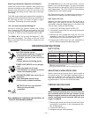
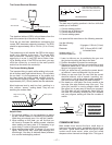
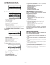
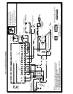
THE GMAW (MIG) WELDING ARC
The drawing below illustrates the GMAW (MIG) weld-
ing arc. Solid wire does not contain fluxes or ingredi-
ents to form its own shielding and no slag forms to
Maximum plate
thickness 5/16” (8.0mm)
protect the molten weld metal. For this reason, a con-
tinuous even flow of shielding gas is needed to protect
the molten weld metal from atmospheric contaminan-
t's such as oxygen and nitrogen. Shielding gas is sup-
plied through the gun and cable assembly through the
gas nozzle, and into the welding zone.
The shielding gas has several other functions besides
protecting the molten weld metal. It helps shape the
cross section of the weld deposit, may increase or
decrease arc temperature, stabilizes the arc, and reg-
ulates penetration.
When comparing the GMAW and FCAW processes,
you can see that the principal difference between the
two lies in the type of shielding used. GMAW uses gas
for shielding, thus we have Gas Metal Arc Welding.
FCAW uses the melting or burning of the core ingredi-
ents for shielding, and is thus termed Self-Shielded
Flux Cored Arc Welding.
The recommended wire for Gas Metal Arc Welding
(MIG) is Lincolnweld
®
.025" L-56 electrode.
Lincolnweld
®
L-56 is capable of welding a wide range
of mild steels in all positions, however, more skill is
required for out-of-position welding with the GMAW
process.
PROCESS SELECTION
By gaining knowledge of the differences between the
two processes, you will be able to select the best
process for the job you have at hand. In selecting a
process, you should consider:
For GMAW (MIG) process
1. Is most of my welding performed on 16 gauge and
lighter materials?
2. Can I afford the extra expense, space, and lack of
portability required for gas cylinders and gas supply
lines?
3. Do I require clean, finished-looking welds?
If you have answered yes to all the above questions,
GMAW may be the process for you. If you have
answered no to any of the above questions then you
should consider using the FCAW process.
For FCAW (Innershield) process
1. Do I want simplicity and portability?
2. Will welding be performed outdoors or under windy
conditions?
3. Do I require good all position welding capability?
4. Will most welding be performed on 16 gauge and
heavier, somewhat rusty or dirty materials?
5. Weld must be cleaned prior to painting.
Gas nozzle
Shielding gas
Weld metal
Solid wire
electrode
Base metal