


7
OPERATION
7
1. POWER SWITCH & LIGHT - Turns power on or
off to the welder. When switched “ON”, the cool-
ing fan runs and the white light will illuminate indi-
cating that the power is on.
2. ELECTRODE/GAS OUTPUT RECEPTACLE - This
Twistmate receptacle provides the electrical connec-
tion to the electrode holder and cable for Stick weld-
ing and a combined electrical and gas connection for
the TIG torch when TIG welding.
3. WORK CABLE - This work cable is factory con-
nected to the welder and is connected to the work
piece to complete the welding circuit. Refer to
Machine Grounding and High Frequency
Interference Protection in the Installation section
of this manual for the proper procedure on ground-
ing the work clamp and work piece to minimize high
frequency interference.
4.
REMOTE CONTROL CONNECTOR - This connector
provides connection for a remote control. See Remote
Control Operation in this section of the manual.
5.
OVER TEMPERATURE LIGHT - If the welder
overheats due to blocked air flow, high ambient air
temperature, or exceeded duty cycle, an internal
thermostat will open disabling the welding output
and this yellow light will illuminate. The cooling fans
will continue to run to cool the unit during this time.
The light will go out when the unit cools and the
thermostat resets.
6. POLARITY SWITCH - Allows you to select between
welding in AC , DC - , or DC+ polar-
ity. In DC + polarity the electrode is positive and the
work clamp is negative. Use DC + for most stick
welding. In DC - the electrode is negative and the
work clamp is positive. Use DC - for TIG welding
stainless steel and mild steel. AC polarity is recom-
mended for TIG welding aluminum.
Do not switch the polarity switch while
welding or damage may result to the
machine.
------------------------------------------------------------------------
SQUARE WAVE TIG 175
CONTROLS AND SETTINGS
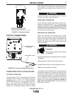
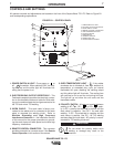
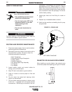
All operator controls and adjustments are located on the front of the Square Wave TIG 175. Refer to Figure B.1
and corresponding explanations.
FIGURE B.1 - CONTROL PANEL
1. POWER SWITCH & LIGHT
2.
ELECTRODE/ GAS OUTPUT RECEPTACLE
3. WORK CABLE & CLAMP
4. REMOTE CONTROL CONNECTOR
5. OVER TEMPERATURE LIGHT
6. POLARITY SWITCH
7. MODE SWITCH
8. CURRENT CONTROL
9. DOWNSLOPE TIME
10. START/CRATER CURRENT
CAUTION
1
7
6
8
5
4
2
3
9
10