


10
OPERATION
10
the positive portion may also cause the electrode to
overheat at high currents causing “tungsten spitting”.
The negative portion of the AC wave offers no cleaning
action but concentrates more heat on the work.The AC
waveform of the Square Wave TIG 175 optimizes
cleaning and heating of the work. The result is the
capability to weld through the complete range of 12 to
175 amperes in AC TIG or DC- TIG requiring only one
electrode, a 3/32” 2% thoriated tungsten.
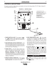
WELDING IN STICK MODE
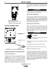
1. Put the electrode holder and cable quick connect
plug into the electrode output receptacle. Turn clock-
wise until tight. Connect the work clamp to the work
piece.
2. Set the TIG/STICK switch to “STICK”.
3. Set the Polarity Switch for the type of electrode
being used (most commonly DC+).
4. Place the electrode in the electrode holder.
5. Turn the power switch to “ON”.
6. Adjust the Current Control to the desired amps.
7. Strike an arc and weld.
NOTE: When the TIG/STICK switch is set to “STICK”
the output is always on when the power switch is on. A
remote control has no effect on the welding current and
the gas flow and high frequency TIG arc starter are dis-
abled.
SQUARE WAVE TIG 175
In Stick Mode the output terminal and
electrode will be electrically hot
whenever the power switch is turned
on.
WARNING
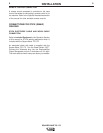
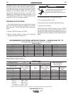
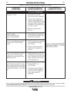
RECOMMENDED ELECTRODE AMPERAGE RANGES - SQUARE WAVE TIG 175
The Square Wave TIG 175 is rated from 10 - 175 Amps.
SMAW Process
ELECTRODE POLARITY 3/32" 1/8" 5/32"
Fleetweld 5P, Fleetweld 5P+ DC+ 40 - 70 75 - 130 90 - 175
Fleetweld 180 DC+ 40 - 80 55 - 110 105 - 135
Fleetweld 37 DC+ 70 - 95 100 - 135 145 - Max
Fleetweld 47 DC- 75 - 95 100 - 145 135 - Max
Jet-LH MR DC+ 85 - 110 110 - 160 130 - Max
Blue Max Stainless DC+ 40 - 80 75 - 110 95 - 110
Red Baron Stainless DC+ 40 - 70 60 - 100 90 - 140
Mild steel procedures are based on recommended procedures listed in C2.10 8/94 and the maximum rating of the Square Wave TIG 175
Jet-LH MR procedures are based on Jet-LH 78 MR
Blue Max procedures are based on C6.1 6/95
Red Baron Procedure are based on ES-503 10/93
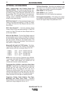
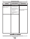
GTAW Process
Electrode Polarity DC- AC Approximate Argon
Electrode Tip Prepration Sharpened Balled Gas Flow Rate
Electrode Type
EWZr C.F.H. (l/min.)
EWTh-1, EWCe-2 EWTh-1, EWTh-2
EWTh-2, EWLa-1 EWP EWCe-2, EWLa-1 Stainless
Electrode Size (in.) EWG EWG Aluminum Steel
.010 Up to 15 A. Up to 10 A. Up to 15 A. 3-8 (2-4) 3-8 (2-4)
.020 Up to 15 A. Up to 15 A. Up to 20 A. 5-10 (3-5) 5-10 (3-5)
.040 Up to 80 A. Up to 40 A. Up to 60 A. 5-10 (3-5) 5-10 (3-5)
1/16 Up to 150 A. Up to 100 A. Up to 130 A. 5-10 (3-5) 9-13 (4-6)
3/32 Up to MAX. A. Up to 160 A. Up to MAX. A. 13-17 (6-8) 11-15 (5-7)
1/8 X Up to MAX. A. X 15-23 (7-11) 11-15 (5-7)
Tungsten electrodes are classified as follows by the American Welding Society (AWS):
Pure..................................EWP........green
+1% Thoria.......................EWTh-1...yellow
+2% Thoria.......................EWTh-2...red
+2% Ceria.........................EWCe-2...orange
+1.5% Lanthana...............EWLa-1...black
+0.15 to 0.40% Zirconia...EWZr.......brown
Ceriated Tungsten is now widely accepted as a substitute for 2% Thoriated Tungsten in AC and DC applications.
MAY96