


D-3
MAINTENANCE
D-3
MAGNUM® 400 DUAL PROCEDURE GUNS
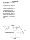
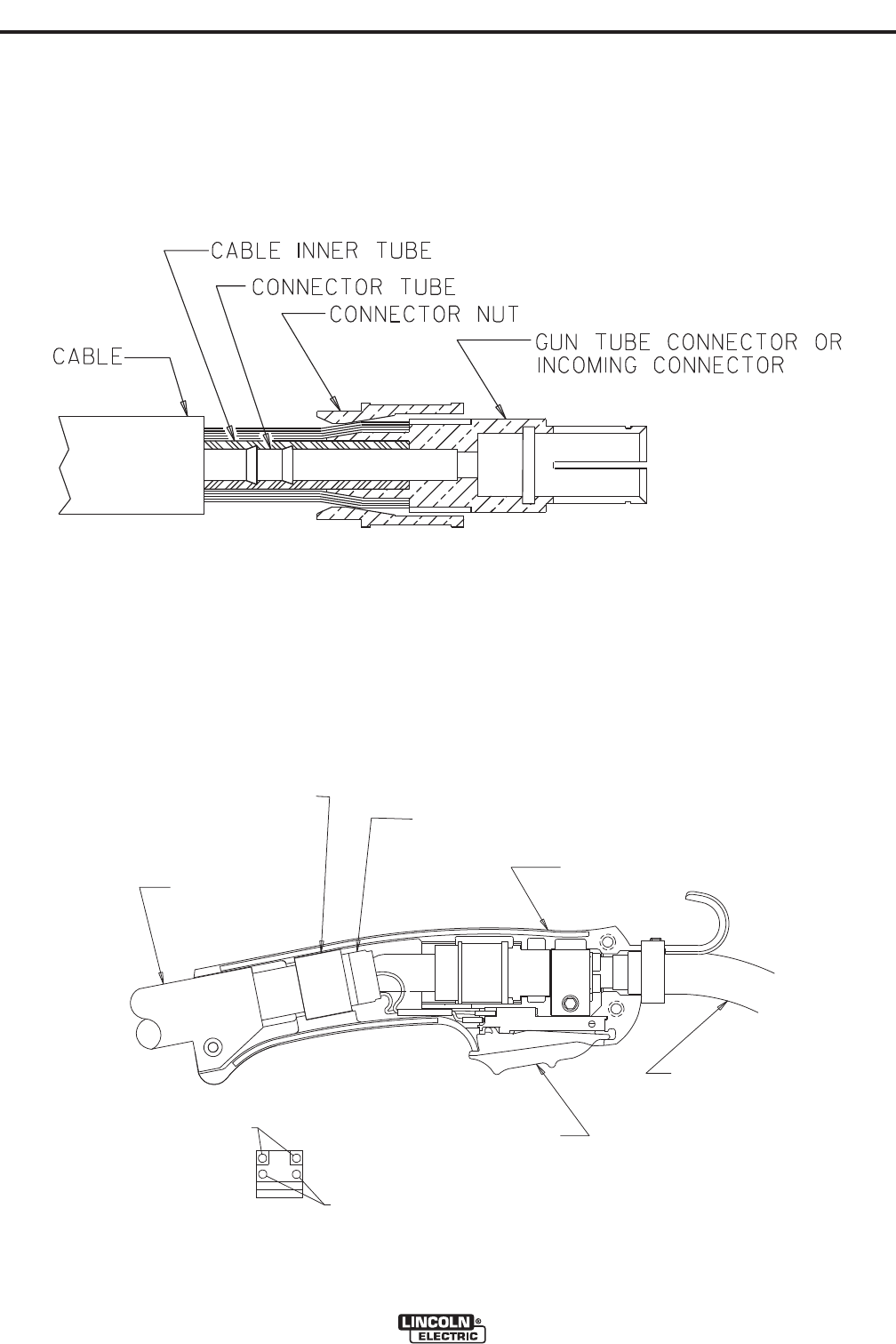
Figure E.3
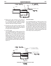
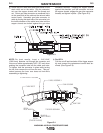
g) Check that the cable boot and both halves of the
strain relief are on the cable. Slip the connector
nut over the copper strands with the thread end
out. Orient gun tube connector so machined flat is
on the same side of the cable as the red and white
control leads. Assemble gun tube connector to
cable by forcing the steel tube of the connector into
the inside diameter of the cable inner tube until the
copper strands are butted against the gun tube
connector shoulder. Keeping the copper strands
against the shoulder, pull the connector nut over
the copper strands, engage the gun tube connector
threads, and tighten in place. (See Figure E.3).
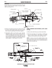
CABLE BOOT
STRAIN RELIEF HOUSING
CABLE ASSEMBLY
GUN HOUSING
GUN TUBE
RED &
BLUE WIRES
BLACK &
WHITE WIRES
DETAIL
(TRIGGER WIRING)
TRIGGER ASSEMBLY
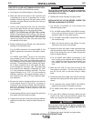
Figure E.4
NOTE: For best results, insert a .219"/240"
(5.6/6.1mm) diameter rod through the connector and
into core of cable approximately 5.00" (127 mm) when
pushing the connector tube into the cable core tube.
To tighten, hold the connector in place while turning
the nut, then remove the rod from the core. This pro-
cedure assures the inner core does not kink while
assembling or tightening.
h) For K574:
Pull the cut-off lead terminals off the trigger assem-
bly and connect the replacement control lead ter-
minals. (See Figure E.4).