


D-4
MAINTENANCE
D-4
MAGNUM® 400 DUAL PROCEDURE GUNS
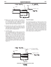
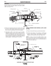
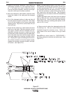
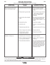
SWITCH WIRES
T0 RED LEAD
CABLE ASSEMBLY
STRAIN RELIEF
STRAIN RELIEF
HOUSING
CABLE BOOT
GUN TUBE
TRIGGER WIRES
GUN HOUSING
TRIGGER ASSEMBLY
TO BLUE LEAD
SWITCH
Figure E.5
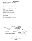
For K1722:
Connect the black lead and the white lead to the gun
trigger. Connect the other leads to the rocker switch
leads. (See Figure E.5).
j) Position the cable boot and strain relief on the cable
so it fits in cable handle cavity and lock the strain
relief in place by pushing the two halves together.
k) Assemble cable in left side of gun handle.
Assemble trigger into the proper handle cavity.(For
K1722 also assemble the rocker switch in the
groves provided in the handle.) Assemble right side
of gun handle and tighten the screws that hold the
handle together. (See Figures E.4 and E.5).
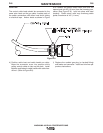
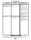
WIRE FEEDER END REPAIR (K574 AND
K1722)
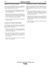
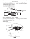
a) Remove the cable liner per previous instructions.
b) Remove the feeder end connector, molded gas
plug (or barbed fitting), cable handle nut, plastic
tailpiece, and connector cover (See Figure E.6).
NOTE: In order to remove the cable handle nut, the
tail of the connector cover must be depressed and the
cable handle nut rotated 1/4 turn counterclockwise as
viewed from the feeder end.
.43 (11 mm) MAX
CONNECTOR COVER
PRESS HERE TO
REMOVE THE CABLE
HANDLE NUT
4.68 (119mm)
Figure E.6