


D-5
MAINTENANCE
D-5
MAGNUM® 400 DUAL PROCEDURE GUNS
c) Remove incoming connector from cable by
unscrewing connector nut from incoming connec-
tor. If the cable inner tube is difficult to remove
from the connector assembly, carefully slit it length-
wise with a knife up to the brass connector.
d) Move the cable boot, cable handle, and strain relief
toward the middle of the cable past the damaged
section.
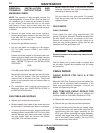
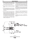
e) Cut off the damaged section of cable and strip off
the outer jacket as shown in Figure E.2. Be careful
not to cut the insulation of the control wires while
stripping jacket. Strip all four control leads .25 (6.4
mm) inch back.
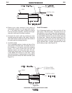
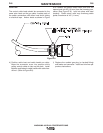
f) Check that the cable boot, cable handle and strain
relief are on the cable. Slip the connector nut over
the copper strands with the threaded end out.
Assemble incoming connector to cable by forcing
the steel tube of the connector into the inside diam-
eter of the cable inner tube until the copper strands
are butted against the incoming connector shoul-
der. Keeping the copper strands against the shoul-
der, pull the connector nut over the copper strands,
engage the incoming connector threads, and tight-
en in place. (See Figure E.3).
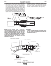
NOTE: For best results, insert a 219"/.240" (5.6-6.1
mm) diameter rod through the connector and into core
of cable approximately 5.00" (127 mm) when pushing
the connector tube into the cable core tube. To tight-
en, hold the connector in place while turning the nut,
then remove the rod from the core. This procedure
assures the inner core does not kink while assembling
or tightening.
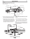
Position the plastic strain relief such that the tapered
end is 4.68 (119 mm) from the incoming connector
(See Figure E.6). Lock into place with steel housing.
Plastic strain relief may overhang cable jacket a maxi-
mum of .43" (11 mm).
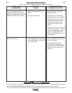
g) Remove control cables from damaged section with
a soldering iron. Be sure control cables are still
threaded through the connector cover. Solder the
base leads of the control cables to the gun cable
leads.
For K574 the control cable for PROCEDURE 1
should be soldered to the black and white leads. (See
Figure E.7).
Figure E.7