


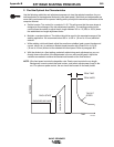
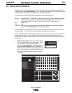

4. “Go Figure” / Make the Waveform Synergic
Weld synergy is established by shaping the 2nd and all subsequent workpoints. Being synergic,
the waveform parameters automatically adjust to programmed data table values. The data table
values are unique for selected wire feed speeds. Thereby, the output of the power source
changes in response to changes in the wire feed speed, as controlled by the Invertec’s WFS
encoder setting. The process of making the waveform synergic involves two procedures;
developing the 2nd workpoint and workpoints interpolation.
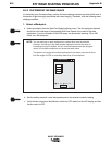
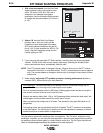
Developing the 2nd Workpoint
Develop the second workpoint in the same manner as the first.
Appendix B B-11
STT WAVE SHAPING PRINCIPLES
WAVE DESIGNER
WorkPoint Editor
WorkPoint Editor
1
0
2
3
90
170
200
225
inch / min meter / min
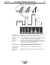
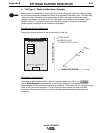
Go Figure
WIRE FEED SPEEDS
WORKPOINT VARIABLE
FIXED VALUE
INTERPOLATED/
EXTRAPOLATED VALUE
28750056
WP0
WP1
WP2
WP3
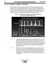
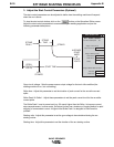
Workpoints Interpolation
After shaping the second waveform, open the workpoint editor and click on the
button. Wave Designer interpolates the waveform parameters for each selected wire feed
speed between the first and second developed workpoints. These steps can be repeated multiple
times to fine tune all the workpoints. The set (fixed) wire feed speeds are those indicated
(checked) in the workpoints listing. Go Figure will interpolate/extrapolate between/from set
workpoints.