


B-2
OPERATION
B-2
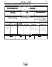
TABLE B.1 – MIG WELDING MATERIAL/GAS COMBINATIONS
Material Gas
Carbon Steel CO2 or Argon/CO2
Low Alloy Steel CO2 or Argon/CO2
FLUX-CORED (INNERSHIELD) WELDING
The recommended electrode for the flux-cored, self-
shielded process is 0.035” (0.9 mm) diameter Lincoln
Innershield NR-211-MP on 1 lbs. (.5 kg) spools.
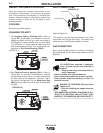
SEQUENCE OF OPERATIONS
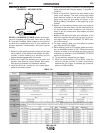
WIRE LOADING AND THREADING
Refer to Figure B.2.
Turn machine power switch to the OFF (“0”) position
before working inside the wire feed enclosure.
Make sure that the wire feed drive roll and the contact
tip of the gun match the diameter and type of wire
used.
1. Push the spool onto the spindle so that the wire
feeds off the bottom of the spool, toward the drive
roll.
2. Push the spool spacer onto the spindle, against the
spool.
3. Slide the spring onto the spool, then press on the
spool lock, turning it clockwise to lock the spool
assembly onto the spindle.
WELDING CAPABILITY
The machine is rated at 70 amps, 17 volts, at 20%
duty cycle on a ten minute basis. It is capable of high-
er output currents at lower duty cycles.
LIMITATIONS
The machine is recommended for welding on mild
steel up to 1/8” thick.
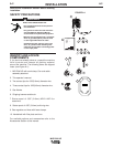
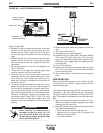
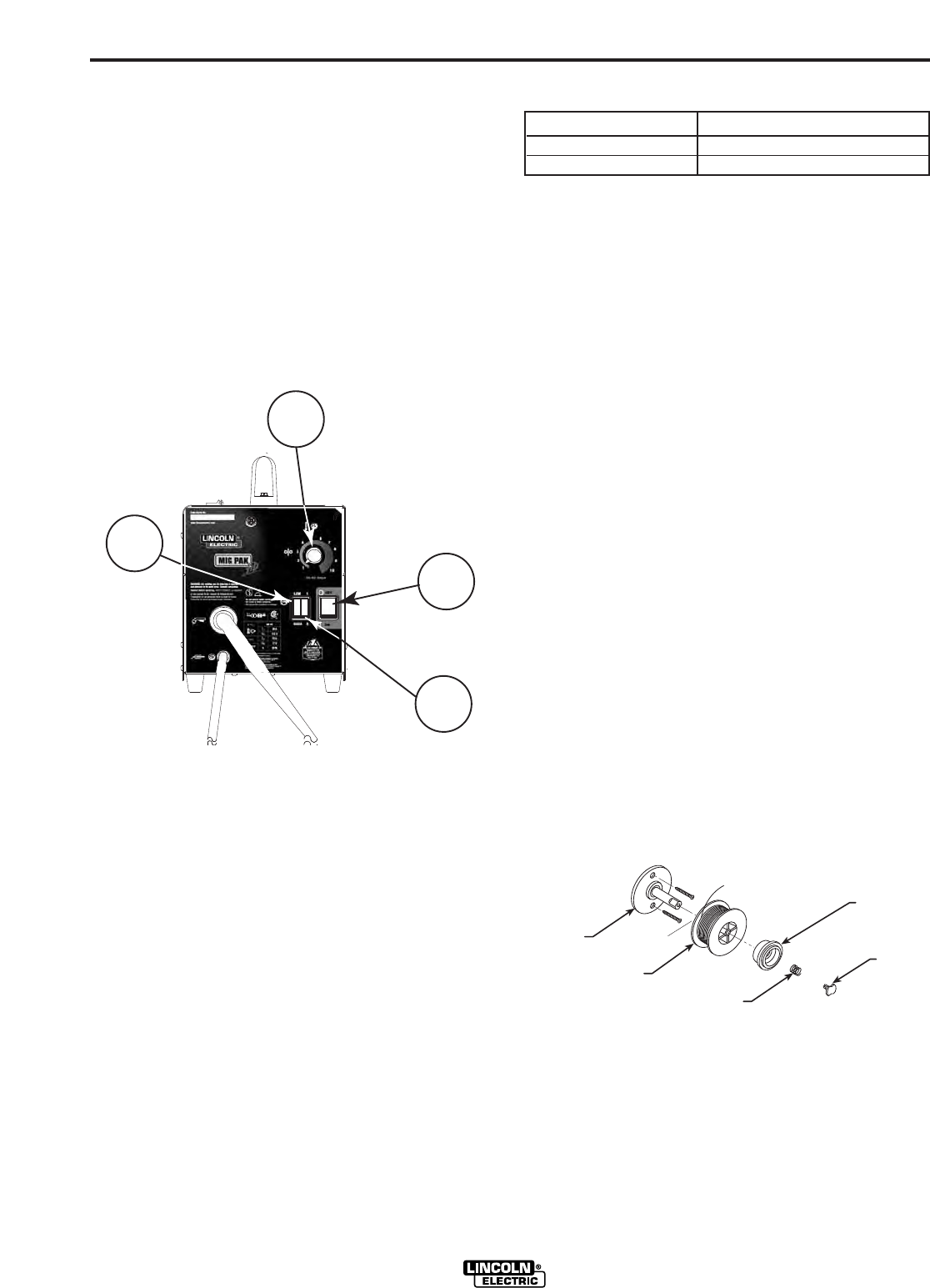
CONTROLS AND SETTINGS
Refer to Figure B.1.
1. Power ON/OFF Switch -When the power is ON
the welding output and wire feeder are ON (“hot”)
when the gun trigger is pressed.
2. Low / High Heat Range Switch. -A rocker switch
control that gives low or high coarse range adjust-
ment of the power source output voltage.
3. 1 – 2 Fine Heat Adjustment Switch. -Allows fine
adjustment of the voltage within the selected Low
or High output range.
4. Wire Speed Control. -Controls the wire feed
speed. Wire speed is not affected when changes
are made in the voltage control.
WELDING OPERATIONS
PROCESS GUIDELINES
MIG WELDING
Table B.1 shows the recommended material/gas
combinations for MIG welding with solid electrodes.
MIG PAK HD
1
4
2
3
FIGURE B.1
SPINDLE
SPRING
SPOOL
LOCK
SPOOL
SPACER
SPOOL
FIGURE B.2