


D-2
MAINTENANCE
D-2
MID PAK HD
CLEANING THE GUN LINER
• Unplug the machine or turn the power switch to the
OFF - “0” position.
• Remove the gas nozzle and contact tip from the
gun.
• Clean the inside diameter with a short piece of wire.
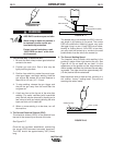
• Clean the cable liner when rough and erratic wire
feeding occur:
Lay the cable out straight. Blow out gently with dry
compressed air through the wire guide tube and check
the condition of the tube. Bend the cable back and
forth, then blow the tube out again. Repeat until
clean.
Excessive pressure at start may cause the dirt to
form a plug.
------------------------------------------------------------------------
CLEANING COMPONENTS AS REQUIRED
• Unplug the machine or turn the power switch to the
OFF - “0” position.
• Blow dirt out of the welder with low pressure air to
eliminate excessive dirt and dust buildup that could
cause the welder to run hot.
• Vacuum accumulated dirt from the gear-box and
wire feed section.
• Inspect the incoming guide tube and clean the
inside diameter if necessary. Replace when exces-
sively worn.
• Replace Contact Tip - when the hole is enlarged or
elongated. (Refer to Changing The Contact Tip, in
this section.)
• Check the condition of the wire feed rollers.
Remove any metallic dust deposited in the feed
area (rollers and entrance and outlet wire guide).
• Check the gas hose and fittings for tightness.
COMPONENT REPLACEMENT
PROCEDURES
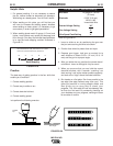
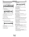
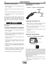
FIGURE D.1 – CONTACT TIP REPLACEMENT
CHANGING THE CONTACT TIP
1. Refer to Figure D.1. Remove the gas nozzle from
the gun by unscrewing it counter-clockwise.
2. Remove the existing contact tip from the gun by
unscrewing it counter-clockwise.
3. Insert and tighten the desired contact tip. Do not
overtighten.
4. Replace the gas nozzle.
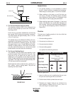
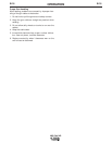
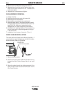
CHANGING THE DRIVE ROLL
FIGURE D.2 – DRIVE ROLL REPLACEMENT
The machine Wire Feed Drive Roll has two grooves;
one for 0.023” - 0.025” (0.6 mm) solid steel electrode
and the other for 0.030” (0.8 mm) solid and 0.035”
(0.9 mm) flux-cored steel electrode. See Figure D.2.
Use the appropriate sized groove for the wire used (as
indicated by the stenciling on the side of the drive roll).
Reverse the drive roll as follows.
Refer to Figure D.2.
1. Make certain the machine power switch is OFF -
“0”.
2. Open the spring loaded pressure arm. Lift up the
idle roll arm.
CAUTION
NOZZLE
CONTACT
TIP
EN50078
1
.
0
-
.
0
4
0
A
L
HANDLE SCREW
UPPER
IDLER ROLL ARM
WIRE FEED
LOWER DRIVE ROLL
INGOING GUIDE TUBE
WIRE
SPRING LOADED