


B-6 OPERATION B-6
AIR VANTAGE® 500 CUMMINS
BREAK-IN PERIOD
The engine used to supply power for your welder is a heavy duty,
industrial engine. It is designed and built for rugged use. It is very
normal for any engine to use small quantities of oil until the break-
in is accomplished. Check the oil level twice a day during the
break-in period. In general this takes 50 to 100 hours of
operation.
IMPORTANT
IN ORDER TO ACCOMPLISH THIS BREAK-IN, THE UNIT
SHOULD BE SUBJECTED TO HEAVY LOADS, WITHIN THE
RATING OF THE MACHINE. AVOID LONG IDLE RUNNING
PERIODS.
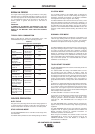
TYPICAL FUEL CONSUMPTION
Refer to Table B.2 for typical fuel consumption of the AIR
VANTAGE® 500 Engine for various operating scenarios.
WELDER OPERATION
DUTY CYCLE
Duty cycle is the percentage of time the load is being applied in a
10 minute period. For example, a 60% duty cycle represents 6
minutes of load and 4 minutes of no load in a 10 minute period.
STICK WELDING MODE
The AIR VANTAGE® 500 can be used with a broad range of DC
stick electrodes.
The MODE switch provides two stick welding settings as follows:
CC-STICK MODE
The CC-STICK position of the MODE switch is designed for
horizontal, vertical-up and over head welding with all types of
electrodes, especially low hydrogen. The OUTPUT CONTROL
knob adjusts the full output range for stick welding.
The ARC CONTROL knob sets the short circuit (arc-force) current
during stick welding. Increasing the number from -10(Soft) to +10
(Crisp) increases the short circuit current and prevents sticking of
the electrode to the plate while welding. This can also increase
spatter. It is recommended that the ARC CONTROL be set to the
minimum number without electrode sticking. Start with the knob
set at 0.
DOWNHILL PIPE MODE
This slope controlled setting is intended for “out-of-position” and
“down hill” pipe welding where the operator would like to control
the current level by changing the arc length. The OUTPUT
CONTROL knob adjusts the full output range for pipe welding.
The ARC CONTROL knob sets the short circuit current (arc-force)
during stick welding to adjust for a soft or a more forceful digging
arc (Crisp). Increasing the number from -10(Soft) to +10(Crisp)
increases the short circuit current which results in a more forceful
digging arc. Typically a forceful digging arc is preferred for root
and hot passes. A softer arc is preferred for fill and cap passes
where weld puddle control and deposition (“stacking” of iron) are
key to fast travel speeds. It is recommended that the ARC
CONTROL be set initially at 0.
TOUCH START TIG MODE
The AIR VANTAGE® 500 can be used in a wide variety of DC TIG
welding applications.
The TOUCH START TIG setting of the MODE switch is for DC
TIG (Tungsten Inert Gas) welding. To initiate a weld, the
OUTPUT CONTROL knob is first set to the desired current and
the tungsten is touched to the work. During the time the tungsten
is touching the work there is very little voltage or current and, in
general, avoids tungsten contamination. Then, the tungsten is
gently lifted off the work in a rocking motion, which establishes the
arc.
To stop the arc, simply lift the TIG torch away from the work piece.
When the arc voltage reaches approximately 30 volts, the arc will
go out and the machine will automatically reset to the touch start
current level. The tungsten may then be retouched to the work
piece to restrike the arc. The arc may also be started and stopped
with an Amptrol or Arc Start Switch.
The ARC CONTROL is not active in the TIG mode.
In general the ‘Touch Start’ feature avoids tungsten contamination
without the use of a Hi-frequency unit. If the use of a high
frequency generator is desired, the K930-2 TIG Module can be
used with the AIR VANTAGE® 500. The settings are for
reference.
The AIR VANTAGE® 500 is equipped with the required R.F.
bypass circuitry for the connection of high frequency generating
equipment.
The AIR VANTAGE® 500 and any high frequency generating
equipment must be properly grounded. See the K930-2 TIG
Module operating manuals for complete instructions on
installation, operation, and maintenance.
When using the TIG Module, the OUTPUT control on the AIR
VANTAGE® 500 is used to set the maximum range of the
CURRENT CONTROL on the TIG Module or an Amptrol if
connected to the TIG Module.
Table B.2
Cummins B3.3 Engine Fuel Consumption
Cummins B3.3 Running Time for
56HP(42Kw) 25GAL.(94.6L)
@1800 RPM (Hours)
Low Idle - .59 Gal./hour 42.4
no load 1425 RPM (2.2 L/hour)
High Idle - .87 Gal./hour 28.7
no load 1900 RPM (3.3 L/hour)
DC CC Weld 2.10 Gal./hour 11.9
Output 500 (7.9 L/hour)
Amps @ 40 Volts
Auxiliary Power 1.44 Gal./hour 17.4
12,000 VA (5.5 L/hour)
Auxiliary Power 2.02 Gal./hour 12.4
20,000 VA (7.6 L/hour)
Air Compressor 1.29 Gal./hour 19.4
60 CFM @ 100 PSI (4.9 L/hour)
Air Compressor
60 CFM @ 100 PSI 2.46 Gal./hour 10.2
and DC, CC Weld (9.3 L/hour)
Output 500 Amps
@40 Volts
Air Compressor
60 CFM @ 100 PSI 1.94 Gal./hour 12.9
and Auxiliary Power (7.3 L/hour)
12,000 VA