


AIR VANTAGE® 500 CUMMINS
F-13 DIAGRAMS F-13
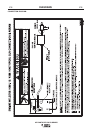
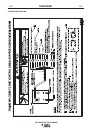
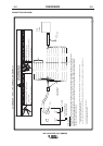
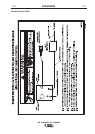
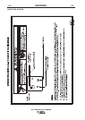
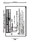
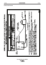
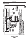
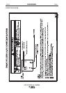
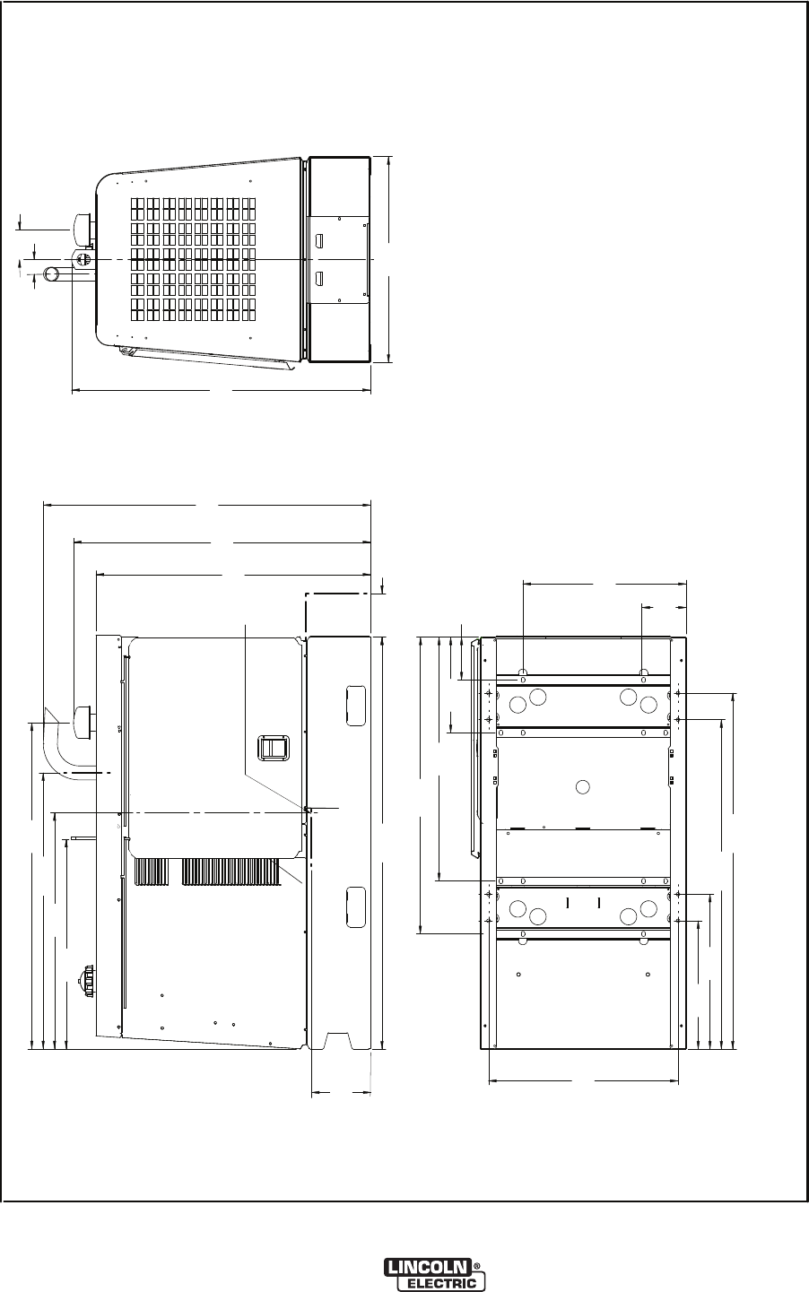
DIMENSION PRINT
M18962-4
B
TRAILER MOUNTING HOLE LOCATIONS.
*
28.99
736.3
19.63
498.6
6.55
166.4
23.69
601.7
50.38
1279.7
54.44
1382.8
14.63
371.6
37.30
947.4
45.38
1152.7
31.50
800.1
45.67
1160
2.24
56.9
3.18
80.8
*
*
*
*
BOTTOM VIEW OF WELDER BASE.
N.A. CENTER OF GRAVITY WITH OIL IN ENGINE, OIL IN COMPRESSOR, COOLANT IN RADIATOR,
AND EMPTY FUEL TANK.
N.A.
6.53
165.9
24.97
634.2
32.08
814.8
42.35
1075.7
52.52
1334
42.00
1066.8
46.35
1177.3
6.56
166.6
63.10
1602.7
9.10
231.1
36.13
917.7
48.92
1242.6
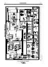
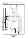
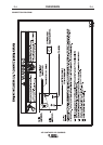
NOTE: This diagram is for reference only. It may not be accurate for all machines covered by this manual. The specific diagram for a particular code is pasted inside the machine on one of the enclosure
panels. If the diagram is illegible, write to the Service Department for a replacement. Give the equipment code number.