


CV-WIRE MODE
Connect a wire feeder to the AIR VANTAGE® 500 and set welder
controls according to the instructions listed earlier in this section.
The AIR VANTAGE® 500 in the ”CV-WIRE” position, permits it
to be used with a broad range of flux cored wire (Innershield and
Outershield) electrodes and solid wires for MIG welding (gas
metal arc welding). Welding can be finely tuned using the “ARC
CONTROL”. Turning the ARC CONTROL clockwise from -
10(soft) to +10(crisp) changes the arc from soft and washed-in to
crisp and narrow. It acts as an inductance/pinch control. The
proper setting depends on the procedure and operator
preference. Start with the knob set at 0.
For any electrodes, including the above recommendations, the
procedures should be kept within the rating of the machine. For
additional electrode information, See www.lincolnelectric.com or
the appropriate Lincoln publication.
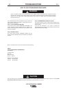
ARC GOUGING
For optimal performance when arc gouging, set the AIR
VANTAGE® 500 “WELD MODE” switch to the “CC - STICK”
position, and the “ARC CONTROL” to 10.
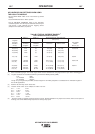
Set the “OUTPUT” knob to adjust output current to the desired
level for the gouging electrode being used according to the
ratings in the following table:
NOTE: If desired the CV mode can be used for Arc Gouging.
* Maximum current setting is limited to the AIR VANTAGE® 500
maximum of 575 Amps.
PARALLELING
When paralleling machines in order to combine their outputs, all
units must be operated in the CC-STICK mode only at the same
output settings. To achieve this, turn the WELD MODE switch to
the CC-STICK position. Operation in other modes may produce
erratic outputs, and large output imbalances between the units.
AUXILIARY POWER OPERATION
If a GFCI receptacle is tripped, See the MAINTENANCE section
for detailed information on testing and resetting the GFCI
receptacle.
Start the engine and set the IDLER control switch to the desired
operating mode. Full power is available regardless of the welding
control settings, if no welding current is being drawn.
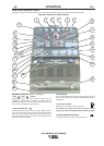
The auxiliary power of the AIR VANTAGE® 500 consists of two 20
Amp-120VAC single phase (5-20R) GFCI duplex receptacles,
one 50 Amp-120/240VAC single phase (14-50R) receptacle and
one 50 Amp 240VAC three phase (15-50R) receptacle. The
120/240VAC receptacle can be split for single phase 120 VAC
operation.
The auxiliary power capacity is 12,000 watts of 60 Hz, single
phase power or 20,000 watts of 60Hz, three phase power. The
auxiliary power capacity rating in watts is equivalent to volt-
amperes at unity power factor. The maximum permissible current
of the 240 VAC output is 50 A. The 240 VAC single phase output
can be split to provide two separate 120 VAC outputs with a
maximum permissible current of 50 A per output to two separate
120 VAC branch circuits. Output voltage is within ± 10% at all
loads up to rated capacity.
NOTE: The two 120V GFCI receptacles and the two 120V circuits
of the 120/240V receptacle are connected to different phases and
cannot
be paralleled.
The auxiliary power receptacles should only be used with three
wire grounded type plugs or approved double insulated tools with
two wire plugs.
The current rating of any plug used with the system must be at
least equal to the current capacity of the associated receptacle.
SIMULTANEOUS WELDING AND AUXILIARY
POWER LOADS
It must be noted that the above auxiliary power ratings are with
no welding load.
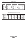
Simultaneous welding and power loads are specified in table B.4.
The permissible currents shown assume that current is being
drawn from either the 120 VAC or 240 VAC supply (not both at the
same time).
ELECTRODE CURRENT RANGE
DIAMETER (DC, electrode positive)
(1/8”) 30-60 Amps
(5/32”) 90-150 Amps
(3/16”) 200-250 Amps
(1/4”) 300-400 Amps
(5/16”) 350-450 Amps
(3/8”) 450-575 Amps*
B-8 OPERATION B-8
AIR VANTAGE® 500 CUMMINS