


A-6
INSTALLATION
POWER FEED™ 25M
A-6
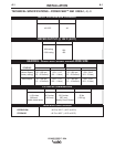
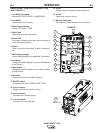
CHANGING THE DRIVE MOTOR GEAR RATIO
• Turn off input power at the weld-
ing power source before installa-
tion or changing drive roll and/or
wire guides.
• Do not touch electrically live parts
such as the wire drive or internal
wiring.
• When feeding with the gun trigger, the electrode
and wire drive mechanism are "hot" to work and
ground and could remain energized several sec-
onds after the gun trigger is released.
• Only qualified personnel should perform this
operation.
------------------------------------------------------------------------
Tools required:
• 1/4" hex key wrench
• 3/4" open end wrench
• 9/16" socket and ratchet wrench
• 7/16" nut driver
• 5/16" nut driver
• Phillips screw driver
1. Turn power off at the welding power source.
2
. Remove the spool of electrode from the wire feeder.
3. Loosen the thumb screw at the wire drive and remove the
welding gun.
4. Remove the outer wire guide, drive rolls and inner wire
guide.
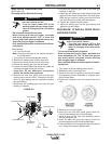
5. Use a 7/16" nut driver to remove the gear cover.
6. Use 9/16" socket and ratchet wrench to remove the lower
drive roll hub retainer. Remove the lower drive roll hub.
7. With a Phillips screwdriver, remove the screw, washer
and collar holding the pinion gear. Remove the pinion
gear.
8. Remove the busbar by unscrewing the bolt using a 3/4"
open end wrench.
9. With a 1/4" hex key wrench, loosen the socket head cap
screw securing the gun bushing. Remove the gun bush-
ing from the wire drive.
10. With a 5/16" nut driver remove the five screws securing
the wire drive panel. Lift out the wire drive panel and
disconnect the molex connections.
11. Using a 5/16" nut driver, remove the four screws secur-
ing the cover.
12. With a Phillips screwdriver, remove the three screws
and lock washers securing the motor. Remove the
motor.
13. Place the motor in the new position.
14. Assemble the three screws and lock washer holding the
wire drive motor.
15. Assemble the molex connections and place the wire
drive assembly inside the wire feeder. Route the gas
hose through the opening in the wire drive panel.
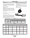
16. Move DIP switch #8 on the Feed head board to the
appropriate position.
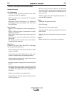
Gear Select DIP Switch #8 Setting Range
Normal Speed ON 50 – 800 ipm
Extra Torque OFF 30 – 400 ipm
17. Place the gun bushing in the wire drive and align the
threaded hole in the gun bushing with the hole in the
feed plate. With a 1/4" hex key, tighten the socket head
cap screw to secure the bushing in the wire drive.
18. Reassemble the busbar and tighten the mounting hard-
ware with a 3/4" open end wrench.
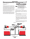
19. Place the new gear on the motor shaft. Secure the gear
to the motor shaft with the collar, washer and screw.
20. Reassemble the lower drive roll hub and lower drive roll
hub retainer.
21. Reassemble the gear cover.
22. Reassemble the inner wire guide, drive rolls and outer
wire guide.
23. Place the welding gun into the gun bushing and secure
with the thumb screw.
WARNING
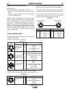
Extra Torque
Gearing
Normal Speed
Gearing
Extra
Torque
G
earing
N
ormal
S
peed
Gearing
400
800
WFS
Feed Force