


A-4A-4
INSTALLATION
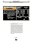
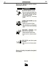
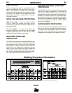
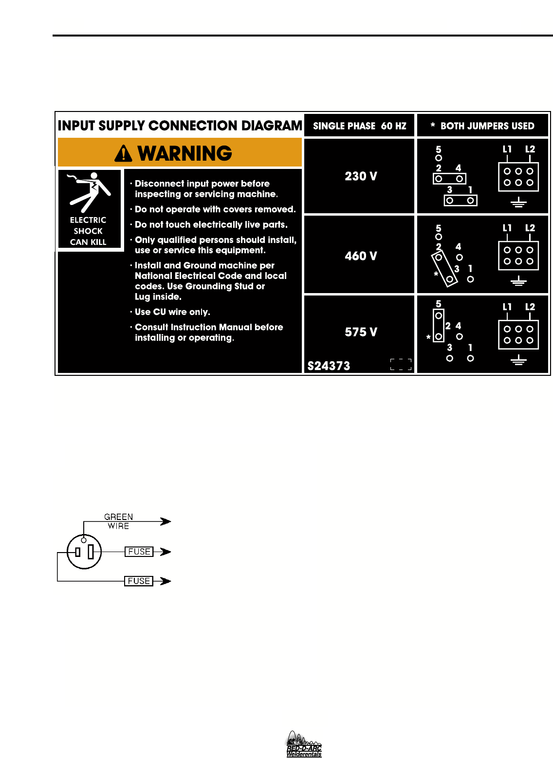
FIGURE A.3 — Receptacle Diagram
CONNECT TO A SYSTEM
GROUNDING WIRE. SEE
THE UNITED STATES
NATIONAL ELECTRICAL
CODE AND/OR LOCAL
CODES FOR OTHER
DETAILS AND MEANS
FOR PROPER GROUND-
ING.
CONNECT TO HOT
WIRES OF A THREE-
WIRE, SINGLE PHASE
SYSTEM OR TO ONE
PHASE OF A TWO OR
THREE PHASE SYSTEM.
OUTPUT POLARITY CONNECTIONS
The welder, as shipped from the factory, is connected
for electrode positive (+) polarity. This is the normal
polarity for GMA welding.
If negative (–) polarity is required, interchange the
connection of the two cables located in the wire drive
compartment near the front panel. The electrode
cable, which is attached to the wire drive, is to be
connected to the negative (–) labeled terminal and
the work lead, which is attached to the work clamp, is
to be connected to the positive (+) labeled terminal.
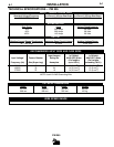
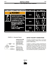
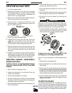
FIGURE A.2 — Triple Voltage Machine Input Connections
PM 255