


B-5B-5
OPERATION
It is not necessary to repeat either of the above proce-
dures each time the unit is powered up. The unit will
remember the run-in mode from the previous power
down and return you to that same state upon your
next power up. Thus, you need only perform one of
the above procedures when you want to change the
run-in mode.
MAKING A WELD
1. Check that the electrode polarity is correct for the
process being used, then turn the power switch
ON.
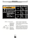
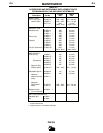
2. Set desired arc voltage and wire speed for the
particular electrode wire, material type and thick-
ness, and gas (for GMAW) being used. Use the
Application Chart on the door inside the wire com-
partment as a quick reference for some common
welding procedures.
3. If Timer Kit is installed, select the desired mode as
described in “Operating Instructions for Timer Kit”
in the Accessories section. Refer to the
Accessories section for additional welding infor-
mation pertaining to Spot mode.
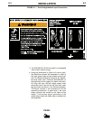
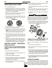
4. Press the trigger to feed the wire electrode
through the gun and cable and then cut the elec-
trode within approximately 3/8" (10 mm) of the
end of the contact tip [3/4" (20 mm) Outershield
®
].
NOTE: If set for slow run-in when the trigger is pulled,
the wire feeder feeds wire at low speed regardless of
the set wire feed speed until the welding arc starts or
1 second has elapsed. This feature enhances starting
and makes it easier to set the stickout. The 1 second
limit permits high speed loading of the gun and cable.
To change run-in mode, see “Setting Run-In Speed” in
this section, if the Timer Kit is not installed, or Timer
Kit Operation section if installed.
5. If welding gas is to be used, turn on the gas sup-
ply and set the required flow rate (typically 25-35
CFH; 12-16 liters/min).
6. When using Innershield electrode, the gas nozzle
may be removed from the insulation on the end of
the gun and replaced with the gasless nozzle.
This will give improved visibility and eliminate the
possibility of the gas nozzle overheating.
7. Connect work cable to metal to be welded. Work
clamp must make good electrical contact to the
work. The work must also be grounded as stated
in “Arc Welding Safety Precautions”.
When using an open arc process, it is necessary
to use correct eye, head, and body protection.
8. Position electrode over joint. End of electrode may
be lightly touching the work.
9. Lower welding helmet, close gun trigger, and
begin welding. Hold the gun so the contact tip to
work distance is about 3/8" (10 mm) [3/4" (20 mm)
for Outershield].
10. To stop welding, release the gun trigger and then
pull the gun away from the work after the arc goes
out.
11. When no more welding is to be done, close valve
on gas cylinder (if used), momentarily operate gun
trigger to release gas pressure, and turn off PM
255.
AVOIDING WIRE FEEDING
PROBLEMS
Wire feeding problems can be avoided by observing
the following gun handling procedures:
a. Do not kink or pull cable around sharp corners.
b. Keep the gun cable as straight as possible when
welding or loading electrode through cable.
c. Do not allow dolly wheels or trucks to run over
cables.
d. Keep cable clean by following maintenance instruc-
tions.
e. Use only clean, rust-free electrode. The Lincoln
electrodes have proper surface lubrication.
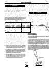
f. Replace contact tip when the arc starts to become
unstable or the contact tip end is fused or
deformed.
g. Keep wire reel spindle brake tension to minimum
required to prevent excess reel over-travel which
may cause wire “loop-offs” from coil.
h. Use proper drive rolls and wire drive idle roll pres-
sure for wire size and type being used.
WARNING
PM 255