


B-4
B-4
OPERATION
FEEDING WIRE ELECTRODE
When triggering, the electrode and drive mecha-
nism are electrically “hot” relative to work and
ground and remain “hot” several seconds after
the gun trigger is released.
NOTE: Check that drive rolls, guide plates and gun
parts are proper for the wire size and type being used.
Refer to Table C.1 in Accessories section.
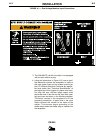
1. Turn the Readi-Reel or spool until the free end of
the electrode is accessible.
2. While securely holding the electrode, cut off the
bent end and straighten the first six inches. (If the
electrode is not properly straightened, it may not
feed properly through the wire drive system).
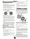
3. Release the pressure on the idle roll by swinging
the adjustable pressure arm down toward the back
of the machine. Lift the cast idle roll assembly and
allow it to sit in an upright position. Leave the outer
wire guide plate installed. Manually feed the wire
through the incoming guide bushing and through
the guide plates (over the drive roll groove). Push a
sufficient wire length to assure that the wire has fed
into the gun and cable assembly without restriction.
Reposition the adjustable pressure arm to its origi-
nal position to apply pressure to the wire.
4. Press gun trigger to feed the electrode wire through
the gun.
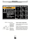
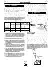
IDLE ROLL PRESSURE SETTING
The idle roll pressure adjustment knob is set at the
factory at the #2 hash mark. This is an approximate
setting. The optimum idle roll pressure varies with
type of wire, wire diameter, surface conditions, lubri-
cation, and hardness. As a general rule, hard wires
may require greater pressure, and soft, or aluminum
wire, may require less pressure than the factory set-
ting. The optimum idle roll setting can be determined
as follows:
1. Press end of gun against a solid object that is elec-
trically isolated from the welder output and press
the gun trigger for several seconds.
2. If the wire “birdnests”, jams or breaks at the drive
roll, the idle roll pressure is too great. Back the
adjustment knob out 1/2 turn, run new wire through
gun, and repeat above steps.
3. If the only result was drive roll slippage, loosen the
adjustment knob on the conductor plate and pull
the gun cable forward about 6" (15 cm). There
should be a slight waviness in the expose wire. If
there is not waviness, the pressure is too low.
Tighten the adjustment knob 1/4 turn, reinstall the
gun cable and repeat the above steps.
SETTING RUN-IN SPEED ON STAN-
DARD POWER MIG FEEDER
FAST OR SLOW RUN-IN MODE SELECTION,
(When Timer Option is not installed)
The PM 255 is factory set for fast run-in mode where
the wire feed will accelerate directly to the preset wire
feed speed when the gun trigger is closed.
Slow run-in mode may also be selected, where it will
initially feed wire at 50 IPM until output current is
sensed or for 1.0 seconds, whichever occurs first.
After which it will accelerate to the preset wire feed
speed.
NOTE: See operating instructions for Timer Option Kit
if it is installed, as it provides its own Run-in operation.
INSTRUCTIONS TO ENTER SLOW RUN-IN
1. Turn power OFF on front panel of PM 255.
2. Turn the wire feed speed dial to minimum, fully
counterclockwise.
3. With the gun trigger closed, turn the power ON at
the front panel of the PM 255.
4. The display will read “SLO run”.
INSTRUCTIONS TO ENTER FAST RUN-IN
1. Turn power OFF on front panel of PM 255.
2. Turn the wire feed speed dial to maximum, fully
clockwise.
3. With the gun trigger closed, turn the power ON at
the front panel of the PM 255.
4. The display will read “FAS run”.
NOTE:
Arc starting characteristics may be effected when
using the fast run-in mode since optimum starting
processes are being overridden.
On the initial trigger closure at power up, no output
power or wire feed will be available until the trigger is
opened and reclosed, regardless of wire feed speed
dial setting.
WARNING
PM 255