


800 AMP TANDEM MIG TORCH
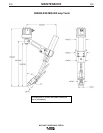
CONTACT TIP AND DIFFUSER
INSTALLATION
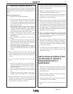
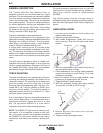
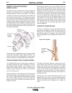
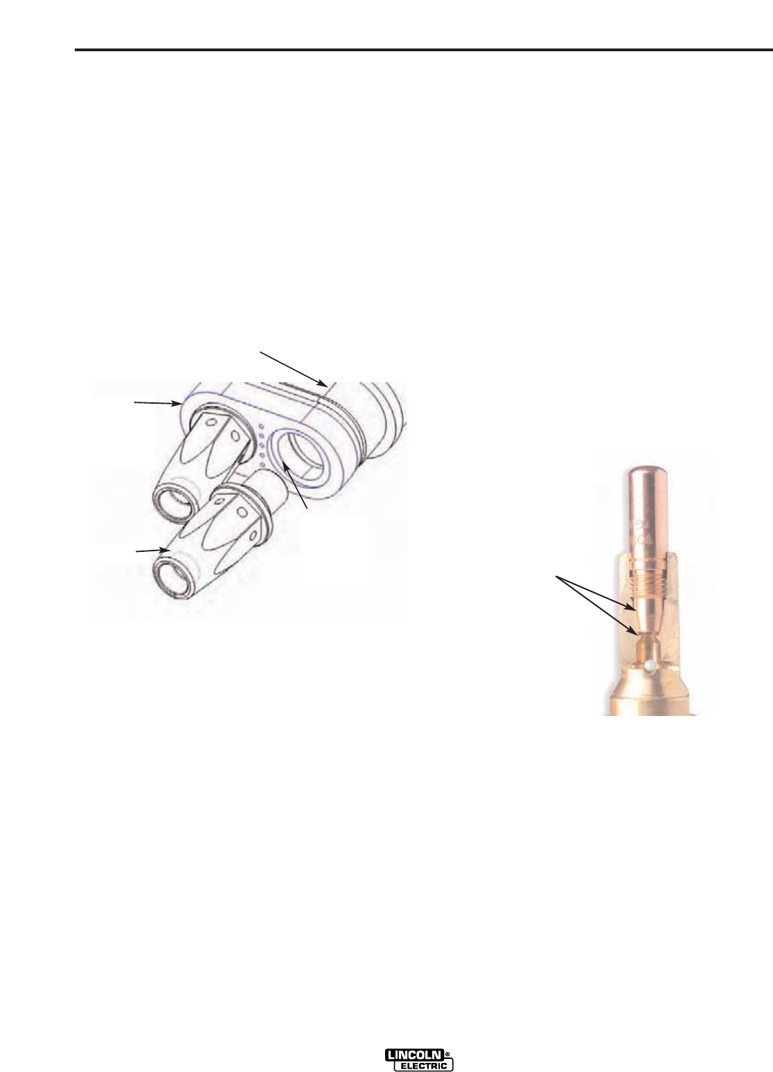
The welding torch is equipped with specially designed
diffusers. The diffuser is of a low profile design to
accommodate the Tandem torch design. The diffuser
is required to provide a current path to the contact tip
and must be secured tightly. The diffuser also serves
as a means to seat and secure the Nozzle Retainer
Insulator. Be sure that the Nozzle Retainer Insulator is
in good condition before replacing the diffusers. Once
it is determined that the insulator is in good condition,
place the insulator against the Retainer Assembly with
the recessed diffuser seating area facing away from
the Retainer Assembly.
Center insulator on gooseneck end and begin thread-
ing diffuser (clockwise) in place, tighten securely. The
contact tip must be firmly tightened to insure proper
current conduction and electrode extension distance.
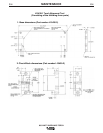
TORCH CONNECTION TO WIRE FEEDER
The Tandem MIG torch is furnished with a power pin
connection designed for direct installation to Lincoln
wire feeders: series Synergic 7 and Power Feed 10
Robotic Wire Feeder. (Power Feed 10 Robotic Wire
Feeders require installing a K1500-1 gun connector
prior to mounting torch.)
Seat the power pin of the welding torch into the power
block of the feeder until tight against power pin shoul-
der. Secure in place with the locking screw provided
with the wire feeder. Welding current of the lead wire
feeder and the trail wire feeder is isolated through the
length of the torch.
Shielding gas delivery must be provided for both the
lead and trail wire electrodes. Gas is delivered to the
diffuser area through the unicable conductor cable
attached to each wire feeder. A 10-inch gas hose
assembly with 5/8-18 barred inert gas fitting is provid-
ed with the wire feeder. The fitting is to be threaded
into the wire feeder female gas outlet fitting. The gas
hose should be slid on to the barbed nipple on the
torch power pin. Using clamp provided, clamp hose to
barbed torch power pin fitting Slide, second clamp
over loose end of hose. Slide the loose end of hose
over the barbed pin at wire feeder gas outlet. Clamp
hose to barbed pin.
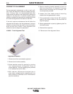
CONTACT TIP SELECTION
The torch is configured to accept two different diffuser
and contact tip designs, a taper lock contact tip and
diffuser and a conventional full threaded contact tip
and diffuser design. As standard, the Tandem MIG
800 Amp Welding Torch is supplied with taper lock dif-
fusers.
The taper lock system features a contact tip and dif-
fuser design that allows for more surface contact
between the contact tip and the diffuser. The added
contact surface provided by the tapering of the seating
areas of the contact tip and diffuser provides an
enlarged current carrying path. The taper system is
designed to provide cooler operation and longer con-
tact tip service life.
Contact tips have a dual thread starting point at 180
degrees from one another. The dual thread starting
points encourages quick installation and the ability to
rotate the contact tip 180 degrees for a longer life
cycle.
A-3
INSTALLATION
A-3
Retainer
Assembly
Diffuser
Nozzle
Retainer
Insulator
Recessed
Diffuser
Seating
Area
Increased
Current
Conducting
Area
Taper Lock System