


C-1
MAINTENANCE
C-1
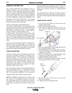
CONTACT TIP REPLACEMENT
Each application will dictate the frequency of contact
tip replacement. Higher amperage, higher duty cycle
operations will require more frequent contact tip
replacement. The condition of the contact tip greatly
effects the welding performance of the Tandem MIG
process. A routine contact tip replacement schedule
should be established and adhered to. For general
operations contact tips should be changed at the
beginning of every shift.
LINER REPLACEMENT
Wire condition, plant environment and the wire con-
sumption rate will dictate how often a liner should be
changed. Welding operations using small diameter
welding wire will require a more frequent contact tip
change interval than operations using larger diameter
welding wires. For general operations using .045 " dia
wire, liners should be changed or cleaned after
approximately 2000 lbs. of wire use.
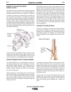
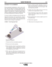
GOOSENECK REPLACEMENT
The Tandem torch is designed with two separate
goosenecks that extend from the mounting and
clamping arm assembly. The goosenecks are config-
ured as a left and a right gooseneck, they are not
interchangeable. Goosenecks require replacement
when they become bent or the outer cover becomes
damaged.
Replacement Procedure
1. Disconnect the water supply and return hoses as
well as the air blast hose.
2. Remove the five hex head screws (5/32" allen)
securing the upper housing of the torch clamping
assembly.
3. Remove torch diffusers, nozzle insulator and
retainer.
4. Lift upper portion of clamping assembly from
lower, slide back the black plastic back housing to
expose gooseneck to unicable connection.
5. Free the connection form the clamping assembly
and with one 1" and one 3/4"" wrench unscrew
gooseneck from unicable brass junction fitting.
6. Replace damaged gooseneck with replacement
gooseneck making sure that the gooseneck is
properly identified as either a left or right goose-
neck. (Left and right are determined by viewing
the torch from the nozzle end.)
7. Place newly assembled unicable and gooseneck
back into the back plastic housing.
8. Place nylon spacer between the two flat surfaces
of the gooseneck brass connector. (Flat surfaces
should be aligned parallel to each other.)
9. Seat back hosing inside the recessed lip of the
lower portion of clamping assembly.
10. Install upper half of clamping assembly after
seating goosenecks and plastic housing.
11. Loosely tighten the five hex head screws of
clamping house.
12. Install gooseneck insulators onto both goose-
necks.
13. Slide nozzle retainer over goosenecks and
gooseneck insulators. (Necks should be free to
rotate as the new retainer is slid into place.)
14. Install nozzle insulator over ends of goosenecks.
15. Install gas diffusers.
16. Install contact tips.
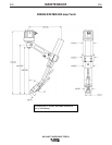
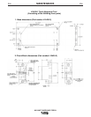
17. Check contact tip alignment. Alignment should
be at equal angles and square to the body of the
torch. (use L10430-1 alignment tool).
18. Once contact tips are aligned, securely tighten
the five hex head screws of clamping assembly.
19. Recheck alignment after tightening the clamping
assembly.
20. Reinstall gas and water hoses.
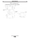
800 AMP TANDEM MIG TORCH