


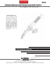
800 AMP TANDEM MIG TORCH
GENERAL DESCRIPTION
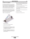
The Tandem MIG 800 Amp Welding Torch is
designed to deliver two wire electrodes to a single
weld pool. The wire electrodes are electrically isolated
from one another providing independent parameter
control of both electrodes. The torch has two separate
wire spacing options. The torch is designed primarily
for robotic applications utilizing wire electrodes in the
diameters of .035 through .062 inches. Torch ratings
are based on the use of shielding gas mixtures con-
taining a minimum of 82% argon gas.
The torch is designed for easy maintenance.
The aluminum construction of the gooseneck outer
jacket and mounting /clamping assemblies defines the
lightweight low profile of the torch. The long goose-
neck design is provided for ease of robot program-
ming for access to restricted welding joints.
A single water-cooling source to circulate water
through the nozzle assembly establishes torch cool-
ing. The aluminum mounting and clamping assembly
serves as an added cooling feature providing a heat
sink to draw heat from the contact tip area and goose-
necks.
The torch may be operated as either a Tandem con-
figuration with two wire electrodes, or as a single wire
torch for special applications. Because of the size of
the Tandem MIG nozzle, during single wire operation
gas delivery through both diffusers is required.
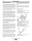
TORCH MOUNTING
The torch mounting arm is an integral part of the torch
mounting and clamping assembly, and should not be
removed or altered. The mounting arm is designed to
place the welding arc at the center line of a robot
mounting plate for programming ease. The arm is fur-
nished with a .647" hole for inserting a S22637 torch
mounting locking wedge. The mounting wedge is
designed to secure the torch to a common .75 " diam-
eter torch collision sensor shaft.
Due to the weight of the torch and rapid movement of
many robotic applications it is recommended that a
rigid mount be used to secure the torch to a robot
arm. The rigid mount S22693-172 is to be used in
conjunction with robot collision sensing software.
NOTE: The S22693-172 rigid mount is a dummy colli-
sion sensor. It is not designed to sense a torch colli-
sion. For proper operator and equipment protection
the S22693-172 rigid mount should only be used in
conjunction with robotic arm collision sensing soft-
ware.
For hard automation applications and for use with
robots that do not have collision sensing software, a
heavy-duty collision sensor is recommended
(M17809).
The collision sensor must be of proper rating to
withstand the high inertia stopping and starting associ-
ated with robot high-speed motion without tripping the
sensor.
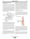
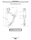
LINER INSTALLATION
1. Lay the torch and cable on a flat surface and
extend cables straight.
2. Remove contact tip and diffuser.
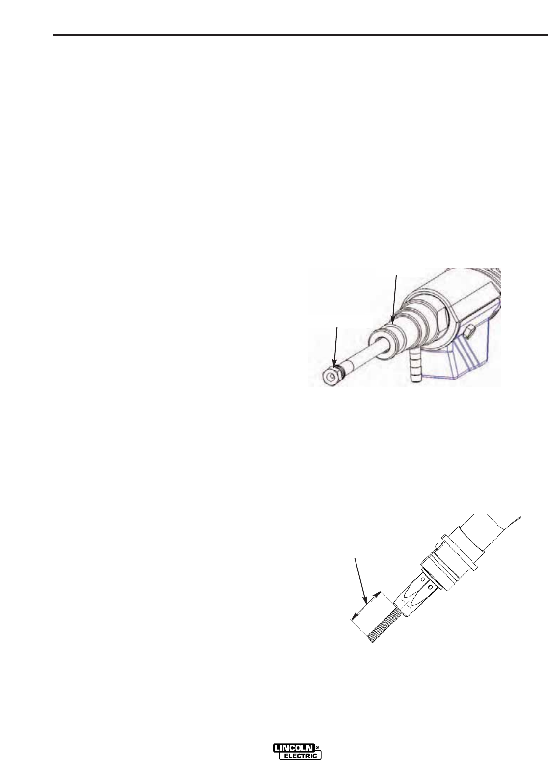
3. With cables straightened, loosen 3/8" liner nut
from power pin. Grip liner with pliers and slowly
remove.
4. With dry compressed air blow cable cavity free of
any accumulated dust or filings.
5. Feed replacement liner through cable assembly
using short strokes to avoid kinking. Twist liner
clockwise if necessary.
6. Seat liner retainer O-ring to inside shoulder bore
of power pin by tightening the 3/8" liner nut.
7. Replace diffusers, tighten securely.
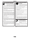
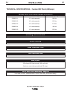
8. With liner extending through torch body (contact
tip removed), trim liner to a 5/16" length.
9. Remove any burr from end of liner that may
obstruct wire feeding.
10. Replace contact tip and gas nozzle.
A-2
INSTALLATION
A-2
Power Pin
3/8" Liner Nut
5/16 "
Extension