


E-2
TROUBLESHOOTING
E-2
SAM400 & 650
Observe all Safety Guidelines detailed throughout this manual
If for any reason you do not understand the test procedures or are unable to perform the tests/repairs safely, contact your Local
Lincoln Authorized Field Service Facility for technical troubleshooting assistance before you proceed.
CAUTION
FUNCTION PROBLEMS
PROBLEMS
(SYMPTOMS)
POSSIBLE CAUSE
RECOMMENDED
COURSE OF ACTION
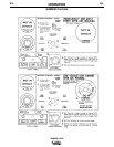
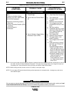
LOSS OF OUTPUT IN ONE MODE
ONLY
(Constant or Variable Voltage
Positions) (For loss in both modes
see the following pages)
These items functioning properly:
1. Alternator
2. Silicon Controlled Rectifier (SCR)
Assembly
3. Control Board #1
4. Generator
1. Test for shorted diode on Three
Phase Bridge.
2. Test for failure of Control Board
#2.
3. Test for Defective Toggle Switch,
Rheostat or Open Circuit
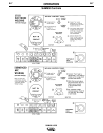
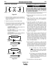
1. Check diodes D7, D8, D9, D10,
D11. (See Diode Test Procedure)
2. a) Turn machine off.
b) Put toggle switch in mode in
question.
c) Remove Control Board #2.
d) Turn voltage control and
portable field control to mini-
mum.
e) Start the machine.
f) If generator builds up, install
new Control Board #2 (Note
A); if it does not build up,
proceed to Step 3.
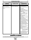
3. a) Turn machine off.
b) Remove Control Board #1
c) Put toggle switch in the
mode in question.
d) Turn voltage control to maxi-
mum.
e) Check continuity of the tog-
gle switch and voltage con-
trol. (Note B).
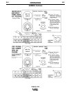
1)Variable Voltage Position
Check continuity from Pin
#76 to Pin #204 on Control
Board #1 connector. Meter
should read a short circuit.
2)Constant Voltage Position
Check continuity from Pin
#76 to Pin #207 on
Control Board #1 connec-
tor. Meter should read a
short circuit.
NOTE A: If at any time either of the Control (PC) boards is replaced, follow the calibration procedure outlined later in this sec-
tion under “Control P.C. Board Calibration Procedure”. The open circuit voltage will be out of range if trimmers are
not properly set. If both trimmers are set at minimum, the machine might lose excitation.
NOTE B: When making continuity checks, use the 1K (X1000) or next higher range.
NOTE C: Do not replace PC boards without following outlined procedure for indicated trouble -- damage may result due to
other defective parts.