


E-3
TROUBLESHOOTING
E-3
SAM400 & 650
Observe all Safety Guidelines detailed throughout this manual
If for any reason you do not understand the test procedures or are unable to perform the tests/repairs safely, contact your Local
Lincoln Authorized Field Service Facility for technical troubleshooting assistance before you proceed.
CAUTION
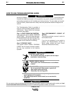
FUNCTION PROBLEMS
PROBLEMS
(SYMPTOMS)
POSSIBLE CAUSE
RECOMMENDED
COURSE OF ACTION
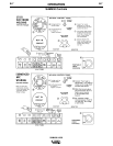
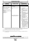
LOSS OF OUTPUT IN BOTH
MODES OF OPERATION
(Constant and Variable Voltage
Positions)
Test Alternator Rotor Voltage (80-
90 Volts DC) Lead #222 to #1
1. If rotor voltage present go to Step 9. If
no rotor voltage go to Step 2.
2. Lightly sand slip rings and reseat brush-
es.
3. Flash rotor fields.
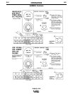
a) Turn machine off.
b) Use a 12 to 24 volt battery.
c) Apply voltage for 15 seconds, negative
lead to #1, positive lead to #222 at alter-
nator terminal strip.
CAUTION: Wrong polarity may dam-
age diodes.
4. Jumper leads #75 to #222 -- replace
alternator thermostats if this produces
output.
5. Continuity check - (Note B Pg. E-2).
a) Remove rotor brushes.
b) Disconnect #212 and #214 from alterna-
tor terminal strip.
c) Remove all leads from #1 and #2 on con-
trol box terminal strip.
d) Remove both Control Boards.
e)
Check continuity from #214 to #1 and #212
to #1 with the positive lead on #214 and
#212. This should read about 27,000 ohms.
If shorted, check C-7 for a short. If all right,
check D5 and D6. See Procedure
6. SCR Bridge Check.-See Procedure
7. Three phase bridge rectifier check.
a) Remove leads from three phase bridge
rectifier assembly and check diodes (D7 -
D8 - D9 - D10 - D11 - D12) See
Procedure
8.
Alternator continuity check - (Note B Pg. E-2).
a) Disconnect lead #212 and #214 and
check winding for continuity.
b) Remove one rotor brush, check continuity
of rotor field.
NOTE: Checking resistance of rotor field
may cancel residual magnetism
in the rotor iron. Repeat Step 3,
"Flash Rotor Fields".
9. If Rotor Voltage is present check voltage
between lead #75 and Pin #227 at the
rear of Control Board #2 connector.
(Approximately 15 to 22 volts DC.)