


E-6
TROUBLESHOOTING
E-6
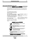
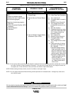
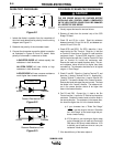
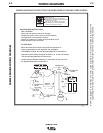
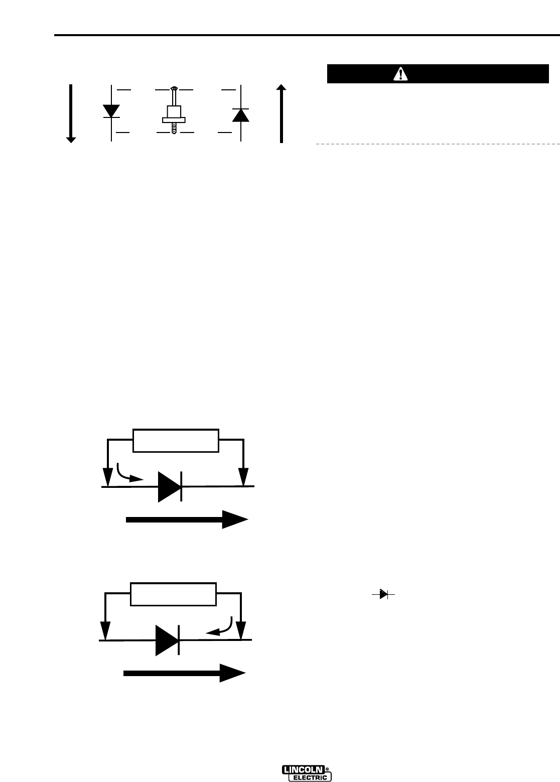
DIODE TEST PROCEDURE
Figure E.1
1. Isolate the diode in question from the remainder of
the circuit and determine its polarity from the wiring
diagram and Figure E.1.
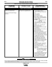
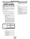
2. Establish the polarity of the ohmmeter leads.
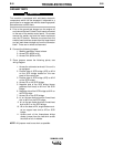
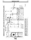
3. Connect the ohmmeter across the diode in question
as illustrated in Figures E.2 and E.3 below. Note
polarity of ohmmeter in reference to diode.
A SHORTED DIODE will indicate equally low
resistance in both directions.
AN OPEN DIODE will have infinite or high
resistance in both directions.
A GOOD DIODE will have a reverse resistance
much higher than forward resistance.
Figure E.2
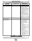
Figure E.3
SCR BRIDGE PC BOARD TEST PROCEDURE
THE SCR BRIDGE SHOULD BE CHECKED BEFORE
INSTALLING NEW CONTROL BOARD. COMPONENTS
ON THE NEW CONTROL BOARD COULD BE DAMAGED
BY A DEFECTIVE SCR BRIDGE.
1. Visually inspect the board for obvious failures.
2. Remove all leads from the terminal strip of the SCR
Bridge PC Board.
3. Check C5 and C6 for a short. Read the resistance
between terminals 210 and 214 for C5, and between ter-
minals 212 and 213 for C6.
4. Check SCR1 and SCR2. For SCR1, attach the (-) ohm-
meter lead to the "Brn" Terminal. Place the (+) lead first
on Terminal 210 and then on Terminal 214 and record the
resistance of each. To check SCR2, keep the (-) lead on
the Brn terminal and with the (+) lead on Terminal 212 and
then on Terminal 214 record the resistances read.
Reverse the leads and repeat the above tests. The sec-
ond resistance values should all be higher than those
recorded first. The ohmmeter should be set in its highest
range or in "Auto Range".
5. Check D1 and D2. Place the (-) lead on Terminal 75, and
place the (+) lead on Terminal 214 for D1. Keeping the (-
) lead on Terminal 75, attach the (+) lead to Terminal 212
to test D2. This tests the diodes in the "forward" direction.
Reverse the leads and repeat the previous test. This tests
the diodes in the "reverse" direction. The resistance val-
ues in the reverse direction should all be higher than
those in the forward direction.
6. Test D3 and R28. Connect the (+) lead to the Brn
Terminal and the (-) lead to the 75 Terminal and record the
resistance. Reverse the meter leads to test the diode in
the reverse direction. The resistance in the reverse direc-
tion should be higher than it is in the forward direction.
a) If your ohmmeter has a "Diode Test Range"
( ), use that range for this test. Otherwise
use "Auto Range" or the lowest range that pro-
duces a meter reading.
b) If D3 is open (or you are using too high a range
on the ohmmeter) you will read only the value of
R28 (about 1200 ohms) in both directions. If D3
is shorted, you will read zero ohms or a very low
resistance in both directions.
7. If the board fails any of the tests, replace it.
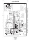
SAM400 & 650
Standard Polarity Reverse Polarity
Conventional
Current Flow
Conventional
Current Flow
Anode
AnodeCathode
Cathode
Symbol Symbol
OHMMETER
Anode
Cathode
Forward Resistance Low
+
-
i
OHMMETER
Anode
Cathode
Reverse Resistance Low
+
-
i
CAUTION