


6
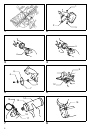
11. Never attempt to cut with the tool held upside
down in a vise. This can lead to serious acci-
dents, because it is extremely dangerous.
(Fig. 1)
12. Before setting the tool down after completing a
cut, be sure that the wheel has come to a com-
plete stop.
SAVE THESE INSTRUCTIONS.
OPERATING INSTRUCTIONS
Installing or removing battery cartridge
1. Always switch off the tool before insertion or removal
of the battery cartridge.
2. For battery cartridges 1200, 1201, 1201A, 1202 or
1202A (Fig. 2)
Always install the set plate when using battery car-
tridges 1200, 1201, 1201A, 1202 or 1202A. Install
the set plate on the tool with the screw and nut pro-
vided as shown in Fig. 2.
3. For battery cartridge 1222, 1233, 1234 or 1235
(Fig. 3)
To remove the battery cartridge, withdraw it from the
tool while pressing the buttons on both sides of the
cartridge.
For battery cartridges 1200, 1201, 1201A 1202
or 1202A (Fig. 4)
To remove the battery cartridge, pull out the set plate
on the tool and grasp both sides of the cartridge
while withdrawing it from the tool.
4. For battery cartridge 1222, 1233, 1234 or 1235
To insert the battery cartridge, align the tongue on
the battery cartridge with the groove in the housing
and slip it until it is locked with a little click.
For battery cartridges 1200, 1201, 1201A, 1202
or 1202A
To insert the battery cartridge, align the tongue on
the battery cartridge with the groove in the housing
and slip it into place. Snap the set plate back into
place. Be sure to close the set plate fully before
using the tool.
5. Do not use force when inserting the battery car-
tridge. If the cartridge does not slide in easily, it is
not being inserted correctly.
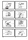
Installing or removing diamond wheel
(Fig. 5 & 6)
Important:
Always be sure that the tool is switched off and the bat-
tery cartridge is removed before installing or removing
the wheel.
To install the wheel, first loosen the bolt with the hex
wrench and remove the bolt and outer flange. Then
mount the wheel, outer flange and bolt. The wheel
should be mounted with the Makita name facing outside.
Press the shaft lock so that the wheel cannot revolve.
Use the hex wrench to tighten the bolt securely.
To remove the wheel, follow the installation procedure in
reverse.
CAUTION:
• When installing the wheel, be sure to tighten the bolt
securely.
• Use only the Makita hex wrench to install or remove the
wheel.
Installing water supply
Attach the tank holder on the tank. The tank holder
should be attached around the portion shown with the
dotted line. Tighten the screw (A) to the extent that the
tank can still turn within the tank holder. (Fig. 7)
Attach the tank holder onto the motor housing. Tighten
the screw (B) securely. (Fig. 8)
Connect the cap on the end of the polyvinyl tube to the
mouth of the tank. Turn the tank clockwise when making
the connection. Then tighten the screw (A) securely to
secure the tank. (Fig. 9)
CAUTION:
If you find the polyvinyl tube is bent like a “V” or has been
strained excessively after installing the water supply,
loosen the screw (B) and adjust the position of the tank to
alleviate the bent, pinched or strained condition.
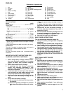
Hex wrench storage (Fig. 10)
When not in use, the hex wrench can be conveniently
stored.
Adjusting the depth of cut (Fig. 11 & 12)
Loosen the clamp screw on the depth guide and move
the base up and down. You can read the depth of cut by
aligning the top of the notch in the depth guide with the
graduations on its right side. (Note: This can be done for
0° bevel cutting only.) At the desired depth of cut, secure
the base by tightening the clamp screw.
CAUTION:
• Use a shallow depth of cut when cutting thin workpiece
for cleaner, safer cuts.
• After adjusting the depth of cut, always tighten the
clamp screw securely.
Bevel cutting (Fig. 13)
Loosen the clamp screw on the bevel scale plate on the
front of the base. Set for the desired angle (0° – 45°) by
tilting accordingly, then tighten the clamp screw securely.
CAUTION:
After adjusting the depth of cut and bevel cutting angle,
be sure to tighten the clamp screw.
Sighting (Fig. 14)
The front of the base is notched to provide two guide
edges. For straight cuts, align the edge with 0° engraved
on it with your cutting line on the workpiece. For 45°
bevel cuts, align the edge with 45° engraved on it with
your cutting line.
Switch action (Fig. 15)
CAUTION:
Before inserting the battery cartridge into the tool, always
check to see that the switch trigger actuates properly and
returns to the “OFF” position when released.
To prevent the trigger from being accidentally pulled, a
lock-off lever is provided. To start the tool, slide the lock-
off lever in the direction of the arrow and pull the trigger.
Release the trigger to stop.
Water supply (Fig. 16)
Remove the cap on the tank and fill through the hole.
Recap the tank. Be sure that the water cock is turned off
when filling the tank with water.
CAUTION:
When filling the tank with water, be careful not to let the
tool get wet.