


5
ENGLISH
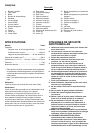
Explanation of general view
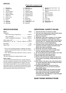
SPECIFICATIONS
Model 7104L
Capacities
Max. hole length (Longitudinal) .....................130 mm
Max. hole depth.............................................155 mm
Width of applicable workpiece........80 mm – 308 mm
Chain speed (min
-1
).................................................300 m
Dimensions (L × W × H) .....512 mm × 298 mm × 513 mm
Net weight................................................................. 17 kg
Safety class ............................................................Class I
• Due to our continuing program of research and devel-
opment, the specifications herein are subject to change
without notice.
• Note: Specifications may differ from country to country.
Intended use
The tool is intended for cutting mortise in wood.
Power supply
The tool should be connected only to a power supply of
the same voltage as indicated on the nameplate, and can
only be operated on single-phase AC supply. This tool
should be grounded while in use to protect the operator
from electric shock. Use only three-wire extension cords
which have three-prong grounding-type plugs and three-
pole receptacles which accept the tool's plug.
ADDITIONAL SAFETY RULES
1. Use this tool only to cut holes in wood.
2. This tool is for cutting holes in flat-surfaced wood.
Never use it for cutting holes in a log.
3. Wear ear protectors.
4. Handle the cutter chain carefully; it is very sharp.
5. Place the workpiece on wood blocks or short
beams to prevent the cutter chain from hitting the
ground, floor, etc., causing damage to the cutter
chain at the time of hole breakthrough.
6. Check the cutter chain carefully for cracks or dam-
age before operation. Replace cracked or dam-
aged cutter chain immediately.
7. Secure the tool to the workpiece firmly.
8. Inspect for and remove nails or foreign matter
from the workpiece before operation.
9. Do not operate the tool with the safety cover open.
10. Do not wear gloves during operation.
11. Keep hands away from moving parts.
12. Remove the tool from the workpiece after opera-
tion to keep it from falling off and possibly caus-
ing injury.
13. Don’t abuse cord. Never yank cord to disconnect
it from the receptacle. Keep cord away from heat,
oil, water and sharp edges.
14. PROPER GROUNDING. This tool should be
grounding while in use to protect the operator
from electric shock.
15. EXTENSION CORDS. Use only three-wire exten-
sion cords which have three-prong grounding-
type plugs and three-pole receptacles which
accept the tool’s plug. Replace or repair damaged
or worn cord immediately.
SAVE THESE INSTRUCTIONS
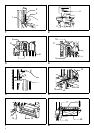
1. Wing bolt
2. Stopper pole
3. Stopper
4. Lock-off button
5. Switch trigger
6. Adjusting screw
7. Chain bar
8. Chain cover
9. Hex bolt
10. Arrow
11. Sprocket
12. Lever (A)
13. Vise lever
14. Rear vise
15. Setting handle
16. Front vise
17. Indicator plate
18. Indication plate
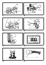
19. Cutting line (A)
20. Cutting line (B)
21. Hook
22. Hex bolts
23. Gauge plate
24. Travel distance (D)
25. Lever (B)
26. Lever (C)
27. Adjusting hex bolt for No. 1 set
position
28. Adjusting hex bolt for No. 2 set
position
29. Original position
30. No.1 set position
31. No.2 set position
32. Ruler
33. Front vise
34. Limit mark
35. Brush holder cap
36. Screwdriver