


6
FUNCTIONAL DESCRIPTION
CAUTION:
• Always be sure that the tool is switched off and
unplugged before adjusting or checking function on the
tool.
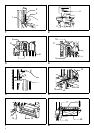
Adjusting depth of cut (Fig. 1)
Loosen the wing bolt on the stopper. Move the stopper to
the desired position and tighten the wing bolt. When tight-
ened, the tip of the wing bolts should contact the flat sur-
face of the stopper pole. The numbers indicated on the
stopper pole are in cm units (3 mm per graduation).
Switch action (Fig. 2)
CAUTION:
• Before plugging in the tool, always check to see that
the switch trigger actuates properly and returns to the
“OFF” position when released.
To prevent the switch trigger from being accidentally
pulled, a lock-off button is provided. To start the tool, push
in the lock-off button and pull the switch trigger. Release
the switch trigger to stop.
ASSEMBLY
CAUTION:
• Always be sure that the tool is switched off and
unplugged before carrying out any work on the tool.
Installing or removing cutter chain (Fig. 3)
WARNING:
• Always be sure that the tool is switched off and
unplugged before installing or removing the cutter
chain.
• Always close the chain cover after installing, removing
or adjusting the cutter chain.
To install the cutter chain, open the chain cover. Loosen
the hex bolt securing the chain bar and the adjusting
screw.
Orient the cutters in the direction of the arrow on the tool
(rotational direction). Attach the cutter chain to the
sprocket first and then to the chain bar. Semitighten the
hex bolt. (Fig. 4)
Turn the adjusting screw to increase the tension on the
cutter chain. Pull the middle of the cutter chain lightly.
When there is a clearance of approx. 5 – 6 mm between
the chain bar and the cutter chain, the tension on the cut-
ter chain is adequate. (Fig. 5)
After adjusting the tension, tighten the hex bolt firmly to
secure the chain bar. Additionally tighten slightly the
adjusting screw. Close the chain cover.
To remove the cutter chain, follow the installation proce-
dures in reverse.
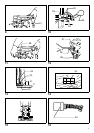
Securing tool to workpiece
Loosen the vise lever and move the rear vise backward.
Place the tool on the workpiece so that the front vise con-
tacts the side of the workpiece. Move the rear vise forward
until the distance between the rear vise and the workpiece
is 3 – 8 mm. Tighten the vise lever to secure the rear vise.
Move the tool so that the “0” on the indication plate is
aligned with the cutting line (A). Push the lever (A) down
fully to secure the workpiece. (Fig. 6 & 7)
Turn the setting handle until the front edge of the yellow
indicator plate is aligned with the cutting line (B). (Fig. 8)
OPERATION
Grasp firmly the grips on either side. Switch on the tool
and wait until the cutter chain attains full speed. Then
release the hook and lower the tool head to cut in the
workpiece. Do not apply excessive pressure to the tool.
This may not only decrease the working efficiency but
also cause a dangerous reaction. Feed slowly at the
beginning of a cutting operation, at the time of hole break-
through and when cutting a knot in the workpiece. After
cutting, gently raise the tool head until you can hook the
tool head back onto the hook. Then switch off the tool.
Raise the lever (A) and remove the tool from the work-
piece. (Fig. 9)
WARNING:
• Always hook the tool head back onto the hook when
not operating the tool.
• Never attempt to cut a twisted or warped workpiece
which the tool is not secured firmly to.
Adjusting indicator plate and indication
plate
The yellow indicator plate and indication plate are factory
adjusted for the standard equipped cutter chain 16.5 mm.
If the alignment is off, for some reason, or when using
another size cutter chain, loosen the screws and adjust
the yellow indicator plate and indication plate.
Enlarging hole
1. Transverse (width) enlargement
A hole can be enlarged transversely by adjusting the
gauge plate. Max. expansion of hole width is 15 mm. (Fig.
10)
Example:
When cutting a hole 25 mm wide using a cutter chain
16.5 mm, proceed as follows:
• Push the lever (B) away from you. Loosen the hex
bolts securing the gauge plate.
• Adjust the gauge plate so that the travel distance
(D) is 8.5 mm; that is, 25 mm – 16.5 mm = 8.5 mm.
Tighten the hex bolts to secure the gauge plate.
• Cut the first hole with the lever (B) pushed away
from you. Then pull the lever (B) toward you and
cut again to enlarge the hole.
NOTE:
• The gauge plate is factory adjusted for cutting a hole
30 mm wide.