


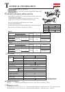

P 7/ 8
R
epair
[3] DISASSEMBLY/ASSEMBLY
[3]-4. Motor Section (cont.)
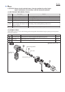
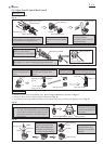
ASSEMBLING
Heat sink
Yoke unit
Brush holder
Armature
Protrusion for fitting to
the notch of Yoke unit
notch for fitting
to Housing set (L)
Fitting the notch of Yoke unit to the protrusion of Housing set (L),
assemble the Motor section.
Notch of
Yoke unit
Notch of
Yoke unit
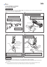
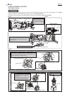
(1) Assemble Armature as illustrated in Fig. 21R.
Note: Pay attention to the position of notch of Yoke unit.
It has to be located on the opposite side of Commutator.
(2) Assemble Brush holder to Armature’s Commutator end.
However, still keep Carbon brush free from the pressure of
Torsion spring of Brush holder in this step.
(2) Assemble the Motor section to Housing set (L) as illustrated
in Figs. 22 and 23.
Commutator
of Armature
Commutator
of Armature
Correct Wrong
Fig. 21R
Fig. 22 Fig. 23
Fig. 21F
Switch side
Housing set (L)
Motor Section
Housing
set (R)
Housing
set (L)
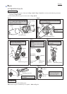
Carbon brush
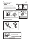
Brush
holder
complete
Mount Brush holder complete on
Commutator so that the angle of two
Carbon brushes can be 90 degrees as
illustrated above.
90 degrees
[3]-5. Assembling F/R Change Lever
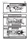
[3]-6. Disassembling Terminal
Protrusion of Switch
for fitting F/R Change
Lever’s concave
Concave of F/R change lever
for fitting to protrusion of
Switch
FET
Fix F/R Change lever to Switch as illustrated in Fig. 24.
Fig. 24
Fig. 25
Stopper
(for firm connection of Flag Terminal)
1. While pushing Stopper with thin screwdriver,
hitch the Flag terminal with the screwdriver.
Flag terminal
Flag terminal for this product is equipped with Stopper for firm connection. Remove Flag terminal as illustrated in Fig. 25.
2. Pull off the Flag terminal.