


P 8/ 8
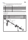
Circuit diagram
White
Red
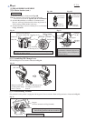
When connecting Lead wires of Brush holder
complete to Switch, connect them as follows.
* Lead wire (black) to M2 Terminal
* Lead wire (red) to M1 Terminal
Terminal
Switch
Switch lever side
LED circuit
FET
Fig. D-1
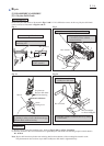
Connector of
LED circuit
Connector of
Switch
Color index of lead wires' sheath
Black
Wiring diagram
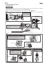
LED circuit has to be put into Housing set (L)
as illustrated below.
Lead wires of LED Circuit has to be guided in Housing set (L)
as illustrated below, and fix them with Lead wire holders.
Connector of LED circuit is connected with
Connector of Switch in the next step.
Lead wire holders
Wiring of LED Circuit
(before setting Switch and other electrical Parts)
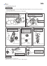
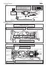
Wiring after setting Switch and other electrical parts
Terminal
Switch
Yoke unit
FET Brush holder completeHeat sink
Lead wire holders
Put the extra portion of
Lead wires in this place.
Fix the Lead wires of Connectors
with these Lead wire holders.
Put the extra portion of
Lead wires in this place.
Connector of
Switch side
Connector of
LED side
Armature
Fig. D-2
Fig. D-3
Brush holder complete
Fix Lead wires of Brush holder complete with these Lead wire holders. And put the Lead
wires of Brush holder complete in the position illustrated above, expanding them between
York unit and Brush holder complete.