


P 3 / 13
[3] -1. Disassembling/ Assembling of Job Light Section
[3] DISASSEMBLING/ ASSEMBLING
DISASSEMBLING
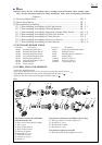
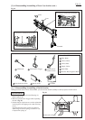
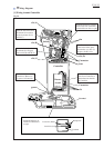
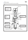
*Shown in Fig. 2 are the parts of Job light section.
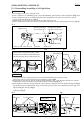
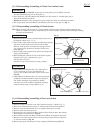
1) Remove Lead cover (on which Ring spring 36 is installed) and Ring spring 29 using a slotted screwdriver. (Figs. 3, 4)
2) Remove Light covers (R) and (L) while pushing the portion designated with the gray circle to unlock the tab on
Light cover (R) from the slot in (L). (Fig. 5)
3) Separate Switch cover from the tool by removing two M4x8 Pan head screws.
4) Remove Lead wires and LED circuit from Lead wire holders and Light cover (R), and disconnect Connector. (Fig. 6)
Pan head screw M4x8
(for fixing Switch cover)
Pan head screw M4x8
(for fixing Ring 38)
Ring spring 29
Light cover (L)
Lead cover Switch cover
Fig. 2
Fig. 3 Fig. 4 Fig. 5
Fig. 6 Fig. 7
ASSEMBLING
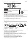
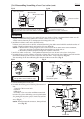
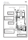
1) Fix Lead wires securely with Lead wire holders, and then install LED circuit on Light cover (R).
At this time, put the sag of Lead wires in place as illustrated to right in Fig. 6.
2) Push the tab on Light cover into the cut in Housing before fastening screws. And then fasten Switch cover with two
M4x8 Pan head screws. Be careful not to pinch the Lead wires at this time. (Figs. 2, 7)
3) Install Light covers (R) and (L) while locking the tab on Light cover (R) in the slot in (L), then Ring spring 29. (Fig. 5)
Ring spring 29 can be easily installed by fixing one end on the groove in Light cover, then pushing toward Light cover
while expanding the other end. (Fig. 8)
4) Being careful not to pinch the Lead wires from LED circuit, install Lead cover (on which Ring spring 36 is installed)
as illustrated in Fig. 9.
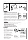
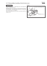
Push the end face of Lead cover using a slotted
screwdriver till it is lifted up as illustrated to left
below. Now Lead cover can be removed by pulling
in the direction o the arrow as illustrated to right.
Push here.
Ring spring 29
LED circuit Lead wire holders Switch cover tab
Put the sag of Lead wires
in this portion.
tab
Light cover (R)