


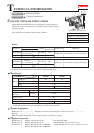

P 3/ 7
Repair
[3] DISASSEMBLY/ASSEMBLY
[3] -3. Locater Section
[3] DISASSEMBLY/ASSEMBLY
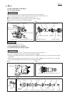
[3] -4. Helical Gear 48, Clutch Section
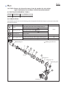
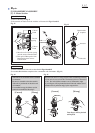
DISASSEMBLING
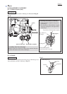
DISASSEMBLING
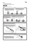
ASSEMBLING
Pull Lock ring strongly. Locater complete and Lock ring can be removed together.
When removing Locater base complete together with Locater complete and Lock ring, etc.:
1 Loosen 4x18 Tapping screws (2 pcs.) and remove Front cover.
2 Loosen M4x25 Pan head screw and pull Locater base complete. (Fig. 2)
Locator section can be removed as illustrated in Fig. 3.
Fig. 2
Fig. 4 Fig. 5
Fig. 3
Do the disassembling step in reverse.
Fig. 7Fig. 6
1
2
M4x25
Pan head screw
M4x25 Pan head screw
4x18 Tapping screws (2 pcs.)
Front cover
Locater base complete
Locater base complete
Leaf spring Ring spring 33 Dust seal ring
Brake pin
Lock ring
Lock ring
Locater complete
Locater complete
1) Pull Lock ring strongly. Locater complete and Lock ring can be removed together.
2) Loosen 4x18 Tapping screws (9 pcs.) and remove Housing R. (Fig. 4)
3) Separate an assembly of Helical gear 48 and Clutch cam, etc. (Fig. 5) from Housing L and remove Ball bearing 608
with 1R269.
4) Remove Leaf spring by hooking and turning it with Long nose pliers. (Fig. 6) Do not lose Steel ball 3.5 on Spindle.
The assembly (Re: Fig. 5) can be removed by hand as illustrated in Fig. 7.
Housing R
4x18 Tapping screws (9 pcs.)
Assembly of Helical gear 48 and Clutch cam, etc.
Leaf spring
Ball bearing
608
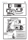
Steel ball 4
(3 pcs.)
Steel ball 4
O ring 18 Leaf spring
Helical
gear 48
Clutch cam C Compression spring 25 Shoulder pin 8-10
Long nose
pliers
Spindle
Ball bearing 608
Flat washer 26 Spindle Sleeve 20 Plane bearing 14Flat washer 25
(2 pcs.)