


P 7/ 7
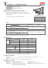
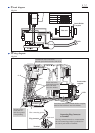
Circuit diagram
Wiring diagram
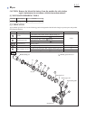
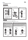
Brush Holder
Complete
LED
Fig. D-1
Fig. D-2
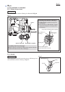
Lead wires (red, black) of Brush holder complete
must be fixed with these lead wire holders.
Do not put any
Lead wire on
this rib to protect
from pinching.
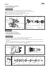
Yoke unit
Circuit
Switch
Terminal
Color index of lead wires' sheath
Black
White
Red
Blue
Switch lead wires (red, black)
must be passed between rib A and rib B.
rib A
LED
rib B
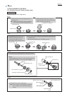
Switch lead wires
(red, black) must be
fixed with these
Lead wire holders.
Brush holder
complete
Terminal
Switch
The flag connector must be so connected that
the wire connecting portion is positioned on
the side of pole marks of Terminal.
Flag connector
Terminal
Connecting Flag Connector
to Terminal
Wire connecting portion
Pole mark