


P 4/ 7
Repair
[3] DISASSEMBLY/ASSEMBLY
[3] -4. Helical Gear 48, Clutch Section (cont.)
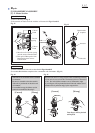
ASSEMBLING
Fig. 9
Fig. 10
Fig. 11
Ball bearing 608
Steel ball 4
(3 pcs)
Steel ball 3.5
Clutch cam C
Helical gear 48
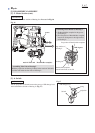
Assembly of Helical gear 48
Spindle
Shoulder pin 8-10
Flat washer 25 (2 pcs)
Sleeve 20
O Ring 18
Plane bearing 14
Gear complete 18-44
Plane bearing 5
(front)
Rubber sleeve 10
Plane bearing 5
(rear)
Flat washer 5
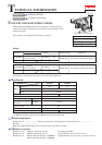
5) Assemble the parts illustrated below into Clutch section.
6) Assemble Gear section to Housing L.
Note: Do not forget to put Flat washer 5 between
Gear complete 18-44 and Plane bearing 5
(front).
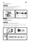
4) Put each Steel ball 4 in the concave portion on the inside wall
of Clutch cam C.
Then assemble Clutch cam C to Helical gear 48.
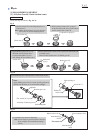
Note:
Apply Makita grease FA.No.2 to the specific portions of
Spindle and Shoulder pin 8-10 illustrated in Fig. 1.
Fig. 8
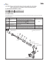
1) Put Flat washer 26 on the flanged portion of
Clutch cam C.
Note: Make sure that there is no space between
Flat washer 26 and the flanged portion.
2) While turning Compression spring 25
in the direction of the arrow, push it down
until it touches Flat washer 26.
Compression spring 25
Flat washer 26
Clutch cam C
Taking the steps described in Fig. 8 to 11.
3) Apply Makita grease FA No.2 to
the inside wall of Clutch cam C
to prevent Steel Ball 4 (3 pcs.)
from falling off from Clutch cam C.